عضویت
عضویت  ورود اعضا
 راهنمای خرید


MTF 55-S0 pages

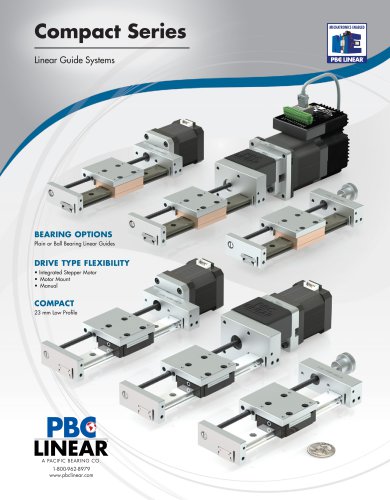
LINEAR ACTUATOR TECHNOLOGY
MT Series
MTF Belt Driven Linear Actuator
The MTF belt driven unit with dual
rail system has the durability to
handle high load capacity. An ideal
fit for vertical applications.
Vertical Lift
Strong Carriage
TECHNICAL DATA
Size
1
in/s
mm
1000
in
39
mm
100
in
3.94
Pulley Drive Ratio
• Ideal for Vertical Movement
m/s
Min. Stroke Length
• Low Friction, Noise & Vibration
55 x 55
Max. Stroke Length
• High Load Capacity - (2) ball guided rail system
mm
Max. Speed
features & benefits
in 2.17 x 2.17
mm
130
in
5.12
Number of Pulley Teeth
26
Max RPM
Key Features
39
460
(1)t Adjustable belt tension
Base Weight
Kg
5.1
lbf
11.2
(2)t Steel reinforced belt capable of handling high loads
Add for 100 mm or 3.94 in of Stroke
Kg
0.51
lbf
1.12
(3)t Anodized aluminum housing and carriage
Max. Load
Fx
N
800
lbf
180
Fy
N
7800
lbf
1753
Fz
N
7800
lbf
1753
Mx
Nm
265
lbf-in
2345
My
Nm
480
lbf-in
4248
Mz
(4) t Ball guided rail system
Nm
480
lbf-in
4248
Ix
4
3
(5)t Motor mount assembly
Max. Moments
(6)t T-slots - ease of mounting
2
1
Moment of Inertia
6
5
4
NOTE:
1. tMoment arms for calculating moments should be measured from the centerline of the extrusion.
2. tLimit switches must be used in order to prevent the carriage from contacting the actuator end blocks, resulting in damage.
3. t25 mm of over-travel has been added to the body length in each direction to allow for carriage over-travel. 25 mm is the
recommended over-travel; although a minimum of 10mm may be specified for special applications.
Iy
Max. Radial Load on Input Shaft
No Load Torque
cm
cm
4
36
46
in
4
0.86
in
4
1.10
N
200
lbf
45
Nm
1.2
lbf-in
10.6
For combined loads, the combined loading
cannot exceed the following formula.