عضویت
عضویت  ورود اعضا
 راهنمای خرید


PRM8-060 pages

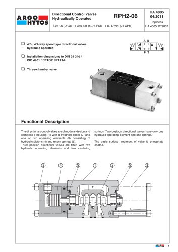
Proportional Directional Control
Valves
PRM8-06
Dn 06 • pmax 350 bar (5076 PSI) • Qmax 140 l/min (37 GPM)
q
Continuous control of both flow rate directions
q
High reliability
q
Indirect control concept with a floating spool
q
Replaces
HA5178 11/2012
High parameters of controlled flow rates
q
HA 5178
2/2014
Installation dimensions to DIN 24 340 /
ISO 4401 / CETOP RP121-H
Functional Description
The proportional directional control valve consists of a
cast-iron body (1), main spool (2), control spool (3), two
auxiliary centring springs (4), two main return springs (5)
and two proportional solenoids (6).
The pilot controlled main spool valve copies the control
spool position, which is given the control current of the
solenoid.
The central position of the main spool is defined by the
auxiliary centring springs.
The solenoids are supplied from an external source,
which should be provided with a current feedback.
In order to achieve optimum operating parameters the
external elektronics should be able to generate an
additional dither - signal.The proportional valve can be
used within the whole range of input pressure, where
jk
within the required continuity of the flow-rate
characteristics and minimum hysteresis is achieved.
The selected concept increases the achieved output
parameters of the proportional valve in comparison to
direct controlled proporcional valve. Further on the valve
shows
a monotone increasing relation between
pressure gradient and flow rate by constant control
current.
Proper functions of the valve are guaranteed only, if the
supply pressure in the “P” channel is present; this
pressure must be always higher than the pressure in the
“T” channel.
The basic surface treatment of the valve housing is
phosphate coated and the operating solenids are zinc
coated.
l
m
1