عضویت
عضویت  ورود اعضا
 راهنمای خرید


Triaxial MEMS Capacitive Analog Accelerometer Module0 pages
SILICON DESIGNS, INC.
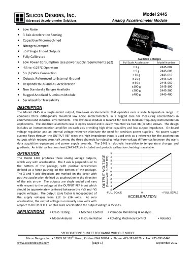
Model 2445
Advanced Accelerometer Solutions
Analog Accelerometer Module
•
Low Noise
•
3 Axis Acceleration Sensing
•
Capacitive Micromachined
•
Nitrogen Damped
•
±5V Single Ended Outputs
•
Fully Calibrated
•
Low Power Consumption (see power supply requirements pg2)
•
-55 to +125°C Operation
•
Six (6) Wire Connection
•
Outputs Referenced to External Ground
•
Responds to DC and AC Acceleration
•
Non Standard g Ranges Available
•
Rugged Anodized Aluminum Module
Serialized for Traceability
•
Available G-Ranges
Full Scale Acceleration
Model Number
±2g
±5g
± 10 g
± 25 g
± 50 g
±100 g
±200 g
±400 g
2445-002
2445-005
2445-010
2445-025
2445-050
2445-100
2445-200
2445-400
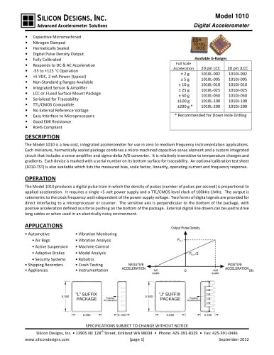
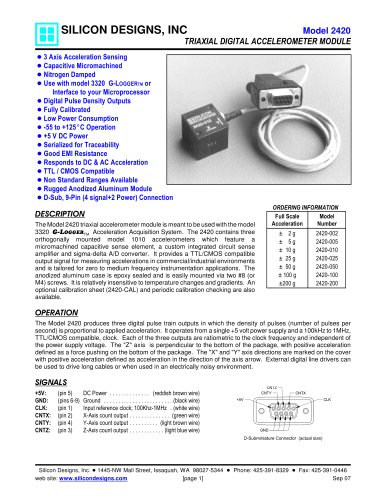
DESCRIPTION
The Model 2445 is a single-ended output, three-axis accelerometer that operates over a wide temperature range. It
combines three orthogonally mounted low noise accelerometers, in a rugged case for measuring accelerations in
commercial and industrial environments. This low noise module is tailored for zero to medium frequency instrumentation
applications. The anodized aluminum case is epoxy sealed and is easily mounted via two #8 (or M4) screws. The design
includes an instrumentation amplifier on each axis providing high drive capability and low output impedance. On-board
voltage regulation and an internal voltage reference eliminate the need for precision power supplies. No power supply
current flows through the OUTPUT REF wire; this high impedance input is used only as a reference for the acceleration
outputs which reduces cross talk among the three channels by rejecting noise from voltage differences between the user's
data acquisition equipment and power supply grounds. The 2445 is relatively insensitive to temperature changes and
gradients. An initial calibration sheet (2445-CAL) is included and periodic calibration checking is available.
5
4
3
2
1
0
-1
-2
-3
-4
-5
-FULL SCALE
(Referenced to OUTPUT REF)
OUTPUT VOLTAGE
OPERATION
The Model 2445 produces three analog voltage outputs,
which vary with acceleration. The Z axis is perpendicular to
the bottom of the package, with positive acceleration
defined as a force pushing on the bottom of the package.
The X and Y axis directions are marked on the cover with
positive acceleration defined as acceleration in the direction
of the axis arrow. The outputs are single ended and vary
with respect to the voltage at the OUTPUT REF input which
should be approximately centered between the +VS and -VS
supply voltages. The output scale factor is independent of
the supply voltages from ±12 to ±16 volts. At zero
acceleration, the output voltage is nominally zero volts with
respect to OUTPUT REF; at ±full scale acceleration the output voltage is ±5 volts.
APPLICATIONS
0
+ FULL SCALE
ACCELERATION
• Crash Testing
• Machine Control
• Vibration Monitoring & Analysis
• Modal Analysis
• Instrumentation
• Rotating Machinery Control
• Robotics
SPECIFICATIONS SUBJECT TO CHANGE WITHOUT NOTICE
th
Silicon Designs, Inc. • 13905 NE 128 Street, Kirkland WA 98034 • Phone: 425-391-8329 • Fax: 425-391-0446
www.silicondesigns.com
[page 1]
September 2012