عضویت
عضویت  ورود اعضا
 راهنمای خرید


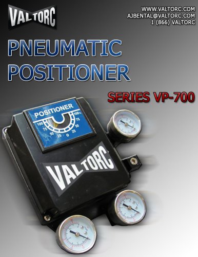
SERIES-EL-930-ELECTRIC-ACTUATOR0 pages
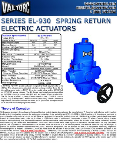
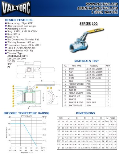
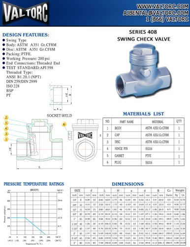
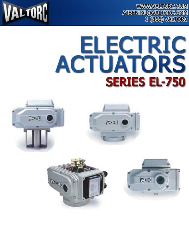
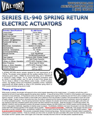
SERIES EL-930 SPRING RETURN
ELECTRIC ACTUATORS
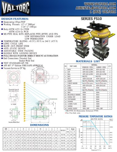
Actuator Specifications Torque Ib/Nm | EL-930 Series 4S0"1bs' SONm | ||
Supply Vollaqe | 24VAC/DC | 120VAC | 230VAC |
Max Inrush Current | 4 OA | 1 3A | |
Running Current | 3 OA | 1 5A | OVA |
Runtime (90 @60/50Hz) | 7 0 sec | 7 C set ,' 9 0 | |
Runtime (90 Sprinq) | 3.0 sec | 3.0 sec | |
Weiqht | 82lbs / 37kq | ||
Mechanical Connections | IS05211 F07 8pt17mm | ||
Electrical Entry | (2) 3/4" NPT | ||
Electrical Terminations | 12-16Ga. | ||
Environmental Ratinq | 4, 4X | ||
Manual Override | 7.6" HandWheel | ||
Control | On/Off/Joq/Proportional | ||
Case material | Aluminum Alloy. Powder Coated | ||
Motor Protection 120vac or 230vac Operation | Split Phase Capacitor 275°F/135°C Thermal F Class | ||
Motor Protection 24vac or 24vdc Operation | 8ruch type DC Motor 275°F/135°C Thermal F Class | ||
Ambient Temperature Operating Range | -22°F to+150°F -30°C to +65°C | ||
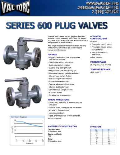
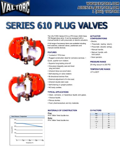
A SPRING RETURN electric actuator designed tor load requirements up to
450'lbs. The actuator comes standard with two auxiliary switches (Form C>, an
internal low power heater, a NEMA 4X environmental rating, and in 120/230VAC
or 24VAC/DC supply voltages. The EL Series mechanical connections utilize
an IS05211 mounting system, size F07 with an 8 point 17mm female drive.
The EL Series is offered in three different control modes ...On/Off (2 position
control), Jog (floating control) and Proportional (modulating control). Application
requirements will dictate whether to utilize a CW (clockwise spring return) or
CCW (counter-clockwise spring return) model.
Theory of Operation
While power is present, the actuator will respond to drive control signals depending on the model chosen. A 2 position unit will drive until it reaches
the full end of travel setting opposite the spring return direction. A Jog unit will drive OPEN, CLOSED or HOLD position until it receives a command to
move otherwise. A Proportional control unit will follow an analog control signal for positioning and will HOLD until a modified control signal is received.
In each of these models a motor brake unit is utilized to HOLD the actuator in position until commanded to move OR a loss of supply voltage. If power
is lost or removed at any time, the brake is released and the mechanical spring mechanism returns the actuator to it's normal (unloaded) position.
Once the spring mechanism has been released, the actuator will not drive under power again until a) the unit has reached it's fail stop (unloaded)
position, and b) power has been restored to the actuator. While the actuator is in it's fail stop position, the MANUAL HANDLE may be employed to
position the actuator anywhere between the UNLOADED and LOADED position, and the actuator will HOLD in that position indefinitely, regardless
of whether power is present. The MANUAL HANDLE must return the actuator to its fully UNLOADED position BEFORE electrical operation of the
actuator will be possible, THIS IS A SAFFTY FFATURF Additionally, if the actuator has been driven electrically to its fully LOADED position, the
MANUAL HANDLE cannot be used to drive the actuator back to its fully UNLOADED position. THIS IS ALSO A SAFETY FEATURE. This prevents
unexpected release of stored spring energy. Remote indication of actuator status is possible by utilizing built-in auxiliary switches. These dry contacts
can show when an actuator has been overridden after power has been restored, indicating the actuator will NOT operate under control again until it
has been manually returned to the full Fail-Safe position (explained above).
"