عضویت
عضویت  ورود اعضا
 راهنمای خرید


MOTORS 145 STK0 pages
Housing internal centering diameter | AH8 | 130 |
Angle wire output / tapped holes | AF | 22°30' |
Housing external centering diameter (fluid cooling) | Bf8 | 153 |
Housing external centering diameter (natural convection) | Bf8 | 145 |
Rotoric internal centering diameter | CH7 | 56 |
Housing internal diameter | De | 78.5 |
Depth of fluid front input / output groove | E1 | 4 |
Width of fluid front input / output groove | E2 | 13.35 |
Position of fluid front I/O groove | E3 | 16.3 |
Rotoric fixation holes | FR | 8xM5 sur 063 |
Housing fixation holes | FS | 8xM5 sur 0136 |
O-ring groove depth | J1 | 2.3 |
O-ring groove width | J2 | 4 |
Position of rear o-ring groove | J3 | 3 |
Position of front o-ring groove | J4 | 10.8 |
Depth of housing internal centering diameter | LA | 2 |
Alignment rotor / housing | P±0.1 | 20.5 |
Maximum rotoric contact diameter | Pmax | 75 |
Depth of fluid rear I/O groove | S1 | 4 |
Width of fluid rear I/O groove | S2 | 13.35 |
Position of fluid rear I/O groove | S3 | 8.5 |
Housing length | LB+0.15 | 92 | 119 | 146 | 173 | 200 | 227 | 254 | 281 |
Rotor length | R +0.15 | 59 | 86 | 113 | 140 | 167 | 194 | 221 | 248 |
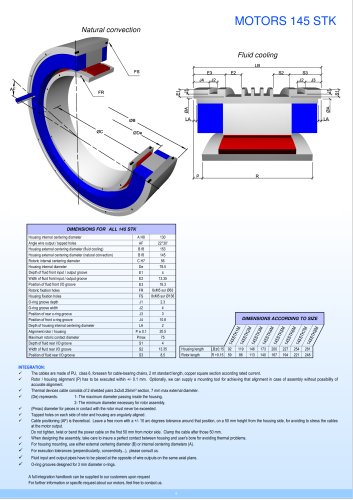
INTEGRATION
nnnnThe cables are made of PL), class 6, foreseen for cable-bearing chains, 2 mt standard length, copper square section according rated current.
nnnnRotor / housing alignment (P) has to be executed within +/- 0.1 mm. Optionally, we can supply a mounting tool for achieving that alignment in case of assembly without possibility of
nnnnaccurate alignment.
nnnnThermal devices cable consists of 2 shielded pairs 2x2x0.25mm2 section, 7 mm max external diameter.
nnnn(De) represents: 1 - The maximum diameter passing inside the housing.
nnnn2- The minimum diameter necessary for rotor assembly.
nnnn(Pmax) diameter for pieces in contact with the rotor must never be exceeded.
nnnnTapped holes on each side of rotor and housing are angularly aligned.
nnnnCable positioning (AF) is theoretical. Leave a free room with a +/-10 arc degrees tolerance around that position, on a 50 mm height from the housing side, for avoiding to stress the cables
nnnnat the motor output.
nnnnDo not tighten, twist or bend the power cable on the first 50 mm from motor side. Clamp the cable after those 50 mm.
nnnnWhen designing the assembly, take care to insure a perfect contact between housing and user's bore for avoiding thermal problems.
nnnnFor housing mounting, use either external centering diameter (B) or internal centering diameters (A).
nnnnFor execution tolerances (perpendicularity, concentricity...), please consult us.
nnnnFluid input and output pipes have to be placed at the opposite of wire outputs on the same axial plane.
nnnnO-ring grooves designed for 3 mm diameter o-rings.
nnnnA full integration handbook can be supplied to our customers upon request
nnnnFor further information or specific request about our motors, feel free to contact us.
"