عضویت
عضویت  ورود اعضا
 راهنمای خرید


visioncivillt0 pages
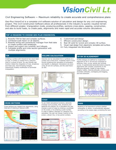
VisionCiv
nnnnCivil Engineering Software — Maximum reliability to create accurate and comprehensive plans
nnnnGeo-Plus VisionCivil is a complete civil software solution of calculation and design for any civil engineering
nnnnproject. This Civil Software allows all professionals in the industry to quickly visualize terrain
nnnnfrom different angles: triangulation mode, producing profiles, sections cross plans, capping, ,
nnnnand also to build roads, to create pads, alignments and make rapid and accurate volume calculations.
nnnnTOP 10 REASONS TO CHOOSE GEO-PLUS VISIONCIVIL
nnnn1. Powerful TIN for fast and complex surfaces.
nnnn2. Combined scale factor on all objects.
nnnn3. Powerful string and connectivity manager from field data
nnnnto create surface with breaklines.
nnnn4. Import and export into LandXML and InRoads.
nnnn5. Complete profile and cross section generation with
nnnnmultiple alignments.
nnnn6. Customized pad design.
nnnn7. Efficient design.
nnnn8. Real 3D solid for tunnel and complex 3D surface.
nnnn9. Visual road design from alignment, template and surface.
nnnn10. Fully integrated into
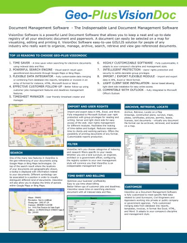
nnnnCreating a surface with VisionCivil has never been
nnnnso easy. A surface is created from a selection
nnnnchart or a group of items. Its user-friendly edit
nnnnfunction makes the integration of lines, breaklines
nnnnand holes easy. Discriminating triangles
nnnninteractively enables modification of perimeter
nnnntriangulation.
nnnnCROSS SECTIONS
nnnnCross-sections are created from alignments, using
nnnnintervals of chaining of desired width.
nnnnVOLUME CALCULATION
nnnnVolumes can be calculated from 2 surfaces or a
nnnnsurface and a fixed level. A detailed report in text
nnnnformat containing the calculation of excavation
nnnnand backfill, is displayed. Calculations are done
nnnnusing 3D and 2D surfaces, and the swell factor
nnnnas well.
nnnn• :i~ ' — r | |||||||
■ | |||||||
i i i | |||||||
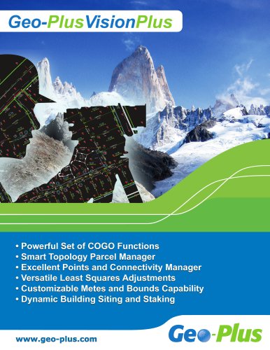
COGO
nnnnTo use COGO calculations functions, elements
nnnnof design such as points, lines, directions and
nnnndistances are entered. For a calculation the user
nnnnchooses a point of origin by clicking a coordinate
nnnnon the screen, or by entering a point number.
nnnnIn order to define a direction or a distance of a
nnnncalculation, the user can choose 2 points on the
nnnnscreen, a drawn line, or two points numbers.
nnnn- --- |=- -3 ■ -a— ft— | |
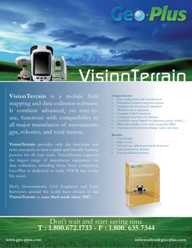
2D OR 3D ALIGNEMENT
nnnnProfiles designs are defined by longitudinal
nnnnalignment of 2D or 3D and are composed of
nnnnpolylines, lines, curves, spirals and verticals
nnnncurves. A sophisticated parameterization presents
nnnnalignments with complex constraints on the
nnnnfollowing elements: length of map sheets,
nnnnheights, widths, chaining altitudes, primary and
nnnnsecondary altitudes, overlapping and begging,
nnnnand end extension.
nnnnPADS
nnnnModeling of all theoretical surfaces whether
nnnnrectangular or others, is automatically adjusted
nnnnaccording to the slopes edge connecting the land.
nnnn- — — - | ||||||||
rut: 1 — | ||||||||
— | ||||||||
* j - | U0H«U | |||||||
■IUU|j| | ||||||||