عضویت
عضویت  ورود اعضا
 راهنمای خرید


Weld ring gaskets0 pages
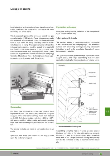
Weld ring gaskets
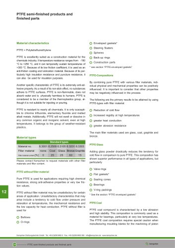
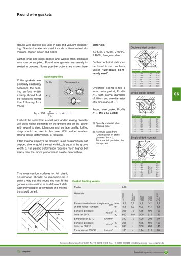
We recommend weld ring gaskets for use in any place where
a welded seal is necessary, due either to the danger of the
medium or the danger presented by a loss of functionality,
but where the connection also needs to be detachable to a
certain degree.
These gaskets are therefore described as being semi-detachable, as the welded sealing joint needs to be undone as
well as the flange bolts.
Weld ring gaskets are generally made of the same or a
related material as the pipe or flange and are only used in
pairs.
06
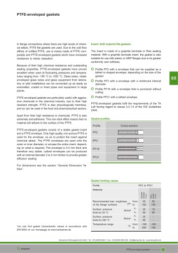
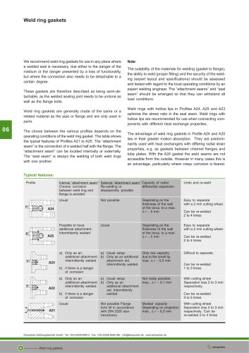
The choice between the various profiles depends on the
operating conditions of the weld ring gasket. The table shows
the typical features of Profiles A21 to A25. The “attachment
seam” is the connection of a welded half with the flange. The
“attachment seam” can be located internally or externally.
The “seal seam” is always the welding of both weld rings
with one another.
Note:
The suitability of the materials for welding (gasket to flange),
the ability to weld (proper fitting) and the security of the welding (expert layout and specifications) should be assessed
and tested with regard to the local operating conditions by an
expert welding engineer. The “attachment seams” and “seal
seam” should be arranged so that they can withstand all
load conditions.
Weld rings with hollow lips in Profiles A24, A25 and A23
optimise the stress ratio in the seal seam. Weld rings with
hollow lips are recommended for use when connecting components with different heat exchange properties.
The advantage of weld ring gaskets in Profile A24 and A25
lies in their greater motion absorption. They are predominantly used with heat exchangers with differing radial strain
properties, e.g. as gaskets between channel flanges and
tube plates. With the A24 gasket the weld seams are not
accessible from the outside. However in many cases this is
an advantage, particularly where creep corrosion is feared.
Typical features:
Profile
Internal "attachment seam" External “attachment seam” Capacity of radial
Crevice corrosion
Re-welding or
differential expansion
between weld ring and
disassembly possible
flange is avoided
Undo and re-weld
Usual
Depending on the
thickness of the wall
of the torus, to a max.
∆ r ~ 5 mm
Easy to separate
with a 2 mm cutting wheel.
Depending on the
thickness of the wall
of the torus, to a max.
∆ r ~ 5 mm
Easy to separate
with a 2 mm cutting wheel.
a) Only as an
a) Usual setup
additional attachment. b) Only as an additional
Intermittently welded
attachment aid.
Intermittently welded
b) if there is a danger
of corrosion
Only low capacity
due to the small lip.
max. ∆ r ~ 0,5 mm
Difficult to separate
a) Only as an
a) Usual setup
additional attachment. b) Only as an
Intermittently welded.
additional attachment
aid. Intermittently
b) if there is a danger
welded
of corrosion
Not really possible.
max.. ∆ r ~ 0,1 mm
With cutting wheel
Separation loss 2 to 3 mm
respectively.
Usual
Modest capacity
Depending on projection
max.. ∆ r ~ 0,3 mm
Possible to have
additional attachment.
Intermittently welded
Not possible
Usual
Not possible Flange
form M in accordance
with DIN 2526 also
necessary
Weld ring gaskets
Can be re-welded
2 to 4 times
Can be re-welded
1 to 3 times
Can be re-welded
3 to 5 times
Kempchen Dichtungstechnik GmbH · Tel. +49 (0)208 8482 0 · Fax. +49 (0)208 8482 285 · info@kempchen.de · www.kempchen.de
86
Can be re-welded
2 to 4 times
With cutting wheel
Separation loss 2 to 3 mm
respectively. Can be
re-welded 2 to 4 times