عضویت
عضویت  ورود اعضا
 راهنمای خرید


ID1102C Dual Channel Rotary Encoder Kit0 pages
ID1102C
Dual Channel
Rotary Encoder Kit
Product data
Features
•
•
•
•
•
•
Highly miniaturized encoder
Differential inductive sensing principle
Insensitive to magnetic interference fields
Robust against oil, water, dust, particles
Programmable resolution and maximum speed
Optional with cable, connector and holder
Applications
•
•
•
•
•
Brushed and brushless motors
Industrial and laboratory automation
Rotary stages
Robotics, assembly equipment
High-speed motion control
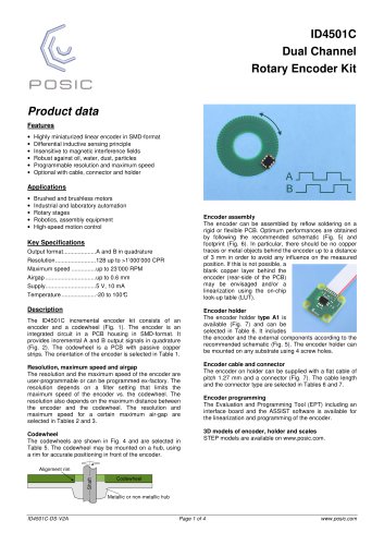
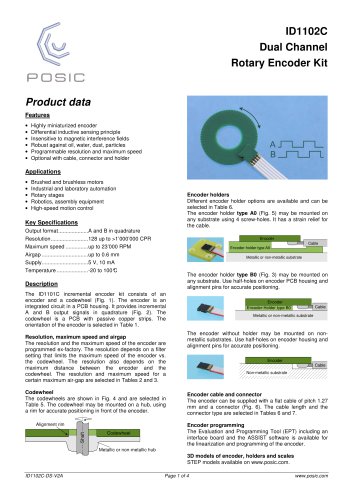
Encoder holders
Different encoder holder options are available and can be
selected in Table 6.
The encoder holder type A0 (Fig. 5) may be mounted on
any substrate using 4 screw-holes. It has a strain relief for
the cable.
Key Specifications
Output format ....................A and B in quadrature
Resolution .........................128 up to >1’000’000 CPR
Maximum speed ...............up to 23’000 RPM
Airgap ...............................up to 0.6 mm
Supply ...............................5 V, 10 mA
Temperature .....................-20 to 100°
C
Encoder
Cable
Encoder-holder type A0
Metallic or non-metallic substrate
The encoder holder type B0 (Fig. 3) may be mounted on
any substrate. Use half-holes on encoder PCB housing and
alignment pins for accurate positioning.
Description
The ID1101C incremental encoder kit consists of an
encoder and a codewheel (Fig. 1). The encoder is an
integrated circuit in a PCB housing. It provides incremental
A and B output signals in quadrature (Fig. 2). The
codewheel is a PCB with passive copper strips. The
orientation of the encoder is selected in Table 1.
Resolution, maximum speed and airgap
The resolution and the maximum speed of the encoder are
programmed ex-factory. The resolution depends on a filter
setting that limits the maximum speed of the encoder vs.
the codewheel. The resolution also depends on the
maximum distance between the encoder and the
codewheel. The resolution and maximum speed for a
certain maximum air-gap are selected in Tables 2 and 3.
Codewheel
The codewheels are shown in Fig. 4 and are selected in
Table 5. The codewheel may be mounted on a hub, using
a rim for accurate positioning in front of the encoder.
Shaft
Alignment rim
Codewheel
Encoder
Encoder-Holder type B0
Cable
Metallic or non-metallic substrate
The encoder without holder may be mounted on nonmetallic substrates. Use half-holes on encoder housing and
alignment pins for accurate positioning.
Encoder
Cable
Non-metallic substrate
Encoder cable and connector
The encoder can be supplied with a flat cable of pitch 1.27
mm and a connector (Fig. 6). The cable length and the
connector type are selected in Tables 6 and 7.
Encoder programming
The Evaluation and Programming Tool (EPT) including an
interface board and the ASSIST software is available for
the linearization and programming of the encoder.
Metallic or non-metallic hub
3D models of encoder, holders and scales
STEP models available on www.posic.com.
ID1102C-DS-V2A
Page 1 of 4
www.posic.com
"