عضویت
عضویت  ورود اعضا
 راهنمای خرید


IT3401L Triple Channel Linear Encoder Kit0 pages
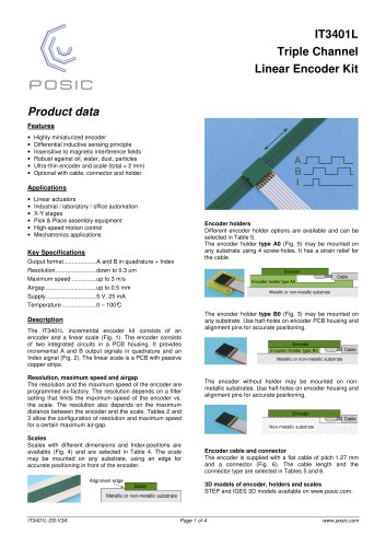
IT3401L
Triple Channel
Linear Encoder Kit
Product data
Features
•
•
•
•
•
•
Highly miniaturized encoder
Differential inductive sensing principle
Insensitive to magnetic interference fields
Robust against oil, water, dust, particles
Ultra-thin encoder and scale (total < 2 mm)
Optional with cable, connector and holder
Applications
•
•
•
•
•
•
Linear actuators
Industrial / laboratory / office automation
X-Y stages
Pick & Place assembly equipment
High-speed motion control
Mechatronics applications
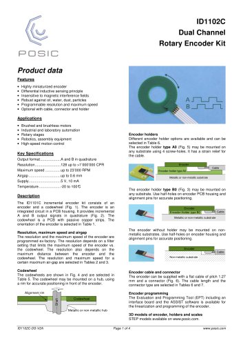
Encoder holders
Different encoder holder options are available and can be
selected in Table 5.
The encoder holder type A0 (Fig. 5) may be mounted on
any substrate using 4 screw-holes. It has a strain relief for
the cable.
Key Specifications
Output format ....................A and B in quadrature + Index
Resolution .........................down to 0.3 um
Maximum speed ...............up to 3 m/s
Airgap ...............................up to 0.5 mm
Supply ...............................5 V, 25 mA
Temperature .....................0 – 100°
C
Encoder
Cable
Encoder-holder type A0
Metallic or non-metallic substrate
Description
The IT3401L incremental encoder kit consists of an
encoder and a linear scale (Fig. 1). The encoder consists
of two integrated circuits in a PCB housing. It provides
incremental A and B output signals in quadrature and an
Index signal (Fig. 2). The linear scale is a PCB with passive
copper strips.
Resolution, maximum speed and airgap
The resolution and the maximum speed of the encoder are
programmed ex-factory. The resolution depends on a filter
setting that limits the maximum speed of the encoder vs.
the scale. The resolution also depends on the maximum
distance between the encoder and the scale. Tables 2 and
3 allow the configuration of resolution and maximum speed
for a certain maximum air-gap.
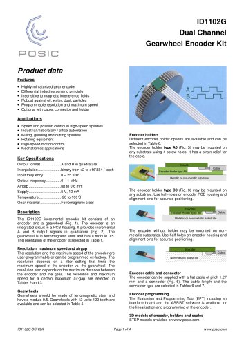
Scales
Scales with different dimensions and Index-positions are
available (Fig. 4) and are selected in Table 4. The scale
may be mounted on any substrate, using an edge for
accurate positioning in front of the encoder.
Alignment edge
Scale
Metallic or non-metallic substrate
IT3401L-DS-V3A
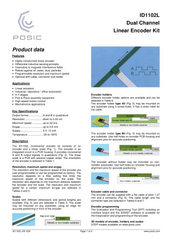
The encoder holder type B0 (Fig. 3) may be mounted on
any substrate. Use half-holes on encoder PCB housing and
alignment pins for accurate positioning.
Encoder
Encoder-Holder type B0
Cable
Metallic or non-metallic substrate
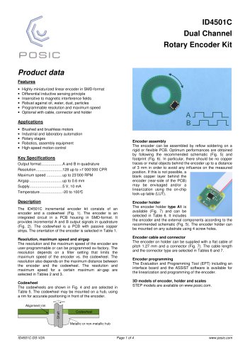
The encoder without holder may be mounted on nonmetallic substrates. Use half-holes on encoder housing and
alignment pins for accurate positioning.
Encoder
Cable
Non-metallic substrate
Encoder cable and connector
The encoder is supplied with a flat cable of pitch 1.27 mm
and a connector (Fig. 6). The cable length and the
connector type are selected in Tables 5 and 6.
3D models of encoder, holders and scales
STEP and IGES 3D models available on www.posic.com.
Page 1 of 4
www.posic.com
"