عضویت
عضویت  ورود اعضا
 راهنمای خرید


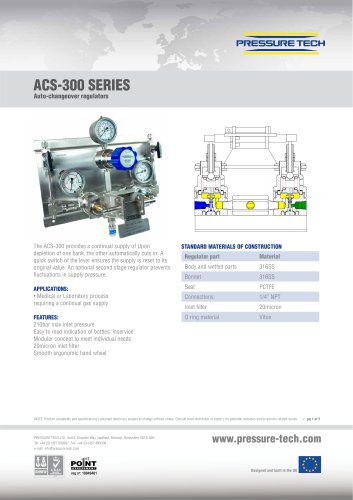
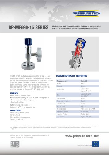
UV-3.50 pages

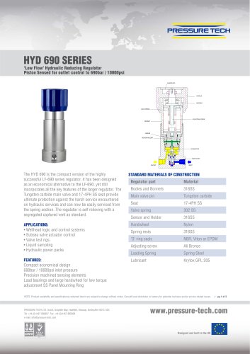
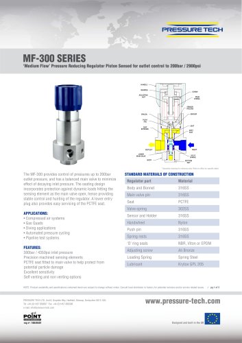
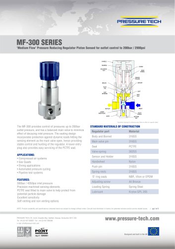
UV 3.5, 3.5S, 3.5Z
Pressure Control Valves
Overflow valves UV 3.5 and 3.5S for liquids and gases up to 130 °C,
UV 3.5Z for steam up to 200 °C
Technical Data
Connection
G 1/2
DN 15 - 25
Nominal Pressure PN 1 - 25
Inlet Pressure
3.5 + 3.5S : 0.005 - 20 bar in 8 ranges
3.5Z
: 0.005 - 12 bar in 7 ranges
Kvs-value
0.14 / 0.4 / 0.9 m3/h
Tightness
acc. VDI/VDE-guideline 2174
(leakage rate K 0.05 % of Kvs-value)
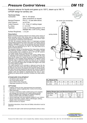
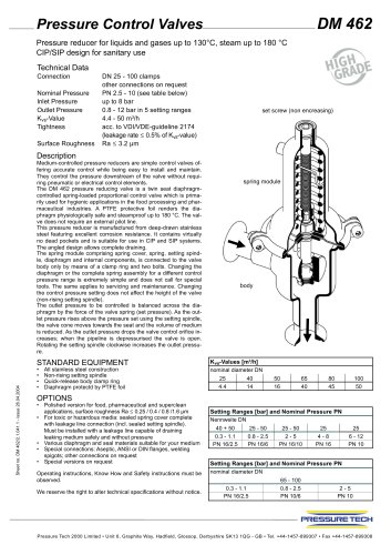
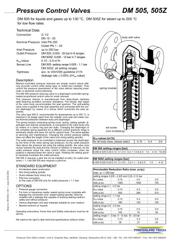
body with valve
Description
Medium-controlled overflow valves are simple control valves offering accurate control while being easy to install and maintain. They
control the pressure upstream of the valve without requiring pneumatic or electrical control elements.
The UV 3.5, UV 3.5S and UV 3.5Z overflow valves are spring-loaded diaphragm-controlled proportional control valves for small volumes. They are manufactured from deep-drawn stainless steel featuring excellent corrosion resistance. The valve cone can be fitted
with a metallic or soft seal.
spring module
The spring module comprising spring cover, spring, setting spindle,
diaphragm and internal components, is connected to the valve
body only by means of a clamp ring and two bolts. Changing the diaphragm or the complete spring assembly for a different control
pressure range is extremely simple and does not call for special
tools. The same applies to servicing and maintenance. Changing
the control pressure setting does not affect the height of the valve
(non-rising setting spindle).
The inlet pressure to be controlled is balanced across the valve
seat by the force of the valve spring (set pressure). As the inlet
pressure falls below the pressure set using the setting spindle, the
valve cone moves towards the seat and the volume of medium is
reduced. As the inlet pressure rises the valve control orifice increases; when the pipeline is depressurised the valve is closed. Rotating the setting spindle clockwise increases the inlet pressure.
For steam applications (UV 3.5 Z) the diaphragm control unit must
be filled with water via the pilot line connections before the valve is
commissioned.
Sheet no. UV 3.5/2.1.041.1 - issue 26.04.2004
The UV 3.5S and UV 3.5Z overflow valves require a pilot line (to be
installed on-site).
STANDARD EQUIPMENT
•
•
•
•
All stainless steel construction
Non-rising setting spindle
Quick-release body clamp ring
Pilot line connection (UV 3.5S and UV 3.5Z)
setting screw
(non encreasing)
Kvs-values [m3/h]
seat
I
0.15
II
0.4
III
0.9
Setting Ranges [bar] UV 3.5 + UV 3.5S
setting range bar
0.005 - 0.025
0.02 - 0.12
0.1 - 0.5
0.2 - 1.1
0.8 - 2.5
1-5
4 - 12
10 - 20
nominal pressure
PN 1
PN 2.5
PN 6
PN 10
PN 25
OPTIONS
• For toxic or hazardous media: sealed spring cover complete
with leakage line connection (incl. sealed setting spindle).
Must be installed with a leakage line capable of draining
leaking medium safely and without pressure
• Various diaphragm and seal materials suitable for
your medium
• Special versions on request
Operating instructions, Know How and Safety instructions must be
observed.
Setting Ranges [bar] UV 3.5Z
setting range bar
0.005 - 0.025
0.02 - 0.12
0.1 - 0.5
0.2 - 1.1
0.8 - 2.5
1-5
4 - 12
nominal pressure
PN 1
PN 2.5
PN 6
PN 10
PN 16
We reserve the right to alter technical specifications without notice.
Pressure Tech 2000 Limited • Unit 6, Graphite Way, Hadfield, Glossop, Derbyshire SK13 1QG - GB • Tel. +44-1457-899307 • Fax +44-1457-899308
"