عضویت
عضویت  ورود اعضا
 راهنمای خرید


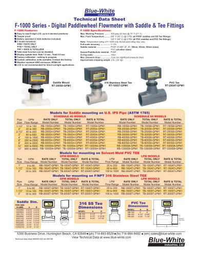
F-2000 Saddle Fittings0 pages

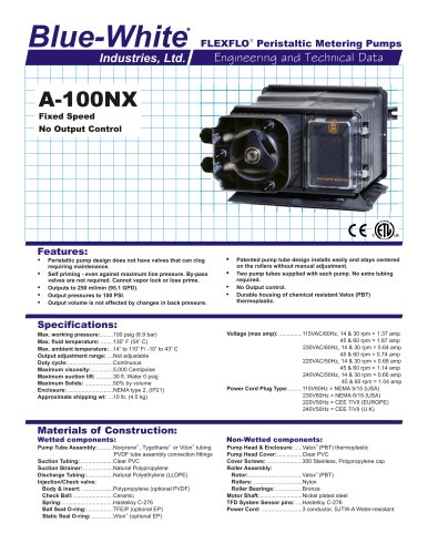
Blue-White
R
Industries, Ltd.
DigiFlo Digital Paddlewheel Meters
Engineering and Technical Data
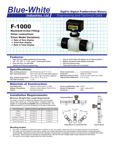
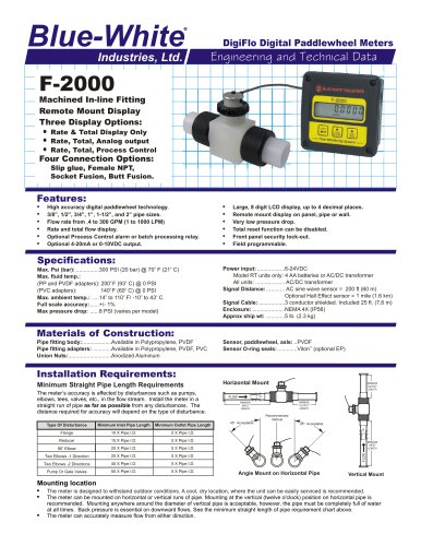
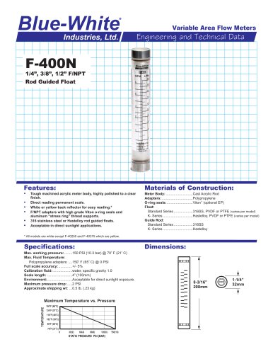
F-2000
Saddle Fitting
Remote Mount Display
Three Display Options:
Rate & Total Display Only
Rate, Total, Analog output
Rate, Total, Process Control
Features:
!
!
!
!
!
!
High accuracy digital paddlewheel technology.
1-1/2” thru 12” and 50mm thru 315mm pipe sizes.
Flow rate from 15 to 8000 GPM (70 to 27000 LPM)
Rate and total flow display.
Optional Process Control alarm or batch processing relay.
Optional 4-20mA or 0-10VDC output.
!
!
!
!
!
!
Large, 8 digit LCD display, up to 4 decimal places.
Remote mount display on panel, pipe or wall.
No significant pressure drop.
Total reset function can be disabled.
Front panel security lock-out.
Field programmable.
Specifications:
Pipe Requirements:
(Inch dimensions) ...........IPS pipe size (ASTM-D-1785)
(Metric dimensions) ........Metric pipe size (DIN 8062)
Max. Psi (bar): ...............300 PSI (20 bar) @ 70o F (21o C)
Max. fluid temp.: ..........PVDF saddle, 200o F (93o C) @ 0 PSI
........................................PVC saddle, 140o F (60o C) @ 0 PSI
Max. ambient temp.: .....14o to 110o F/ -10o to 43o C
Note: Temperature & Pressure ratings of meter only. Actual pipe rating may vary.
Max pressure drop: ......0 PSI (No significant pressure drop)
Full scale accuracy: ......+/- 1%
Power input: ..................6-24VDC
Model RT units only: 4 AA batteries or AC/DC transformer
All units: ................... AC/DC transformer
Signal Distance: ............ AC sine wave sensor = 200 ft (60 m)
Optional Hall Effect sensor = 1 mile (1.6 km)
Signal Cable: .................3 conductor shielded. Included 25 ft. (7,6 m)
Enclosure: .....................NEMA 4X (Ip56)
Approx ship wt: ............4 lb. (1.8 kg)
Materials of Construction:
Saddle: ................................... ...............PVDF or PVC
Sensor, paddlewheel, axle: ..................PVDF
q
Sensor & saddle O-ring seals: .............Viton (optional EP)
Pipe Clamp: ...........................................300 series Stainless Steel
Installation Requirements:
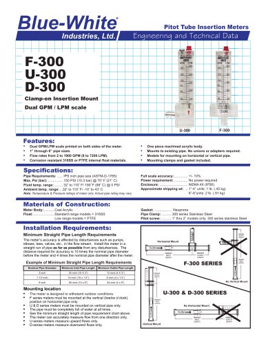
Minimum Straight Pipe Length Requirements
The meter’s accuracy is affected by disturbances such as pumps,
elbows, tees, valves, etc., in the flow stream. Install the meter in a
straight run of pipe as far as possible from any disturbances. The
distance required for accuracy will depend on the type of disturbance.
MINIMUM
OUTPUT
LENGTH
Horizontal Mount
FLOW
I.D.
MINIMUM
INPUT
LENGTH
MINIMUM
OUTPUT
LENGTH
Recommended
Vertical
Minimum Inlet Pipe Length
Minimum Outlet Pipe Length
Flange
10 X Pipe I.D.
5 X Pipe I.D.
Reducer
15 X Pipe I.D.
45° Acceptable
5 X Pipe I.D.
o
20 X Pipe I.D.
5 X Pipe I.D.
25 X Pipe I.D.
5 X Pipe I.D.
Two Elbows -2 Directions
40 X Pipe I.D.
5 X Pipe I.D.
Pump Or Gate Valves
50 X Pipe I.D.
5 X Pipe I.D.
MINIMUM
INPUT
LENGTH
FLOW
90 Elbow
Two Elbows -1 Direction
I.D.
Type Of Disturbance
45° Acceptable
Angle Mount on Horizontal Pipe
Vertical Mount
Mounting location
!
!
!
The meter is designed to withstand outdoor conditions. A cool, dry location, where the unit can be easily serviced is recommended.
The meter can be mounted on horizontal or vertical runs of pipe. Mounting at the vertical (twelve o'clock) position on horizontal pipe is
recommended. Mounting anywhere around the diameter of vertical pipe is acceptable, however, the pipe must be completely full of water
at all times. Back pressure is essential on downward flows. See the minimum straight length of pipe requirement chart above.
The meter can accurately measure flow from either direction.