عضویت
عضویت  ورود اعضا
 راهنمای خرید


Choosing connectors and wiring VSD-A0 pages
Making connections to VSD-A documentation Ver. 1
Introduction
The purpose of this document is to help choosing correct connectors and making robust wiring to VSD-A
drive.
Signal connectors
VSD-A has several pin headers with 0.1” pin pitch (2.54 mm). These pin headers are best mated to IDC
connectors that can be attached to a standard ribbon cable without making solder connections. IDC
connectors are available in most electronic component distributors.
Illustration 1: IDC connectors with 0.1" (2.54
mm) pin spacing
Interfacing motor & encoder
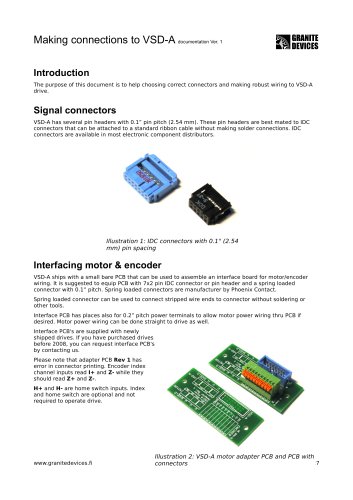
VSD-A ships with a small bare PCB that can be used to assemble an interface board for motor/encoder
wiring. It is suggested to equip PCB with 7x2 pin IDC connector or pin header and a spring loaded
connector with 0.1” pitch. Spring loaded connectors are manufacturer by Phoenix Contact.
Spring loaded connector can be used to connect stripped wire ends to connector without soldering or
other tools.
Interface PCB has places also for 0.2” pitch power terminals to allow motor power wiring thru PCB if
desired. Motor power wiring can be done straight to drive as well.
Interface PCB's are supplied with newly
shipped drives. If you have purchased drives
before 2008, you can request interface PCB's
by contacting us.
Please note that adapter PCB Rev 1 has
error in connector printing. Encoder index
channel inputs read I+ and Z- while they
should read Z+ and Z-.
H+ and H- are home switch inputs. Index
and home switch are optional and not
required to operate drive.
www.granitedevices.fi
Illustration 2: VSD-A motor adapter PCB and PCB with
1/2
2007-04-27
connectors