عضویت
عضویت  ورود اعضا
 راهنمای خرید


LDL2 Series0 pages

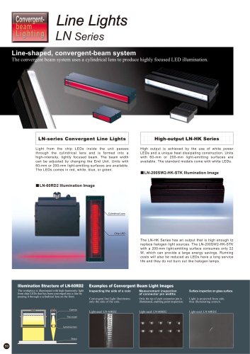
Bar Lights
LDL2 Series
Highly functional Bar Lights
New mounting methods for Installation flexibility.
Flexibility of Mounting
to Match Your Site Environment
A Broad Range of Applications
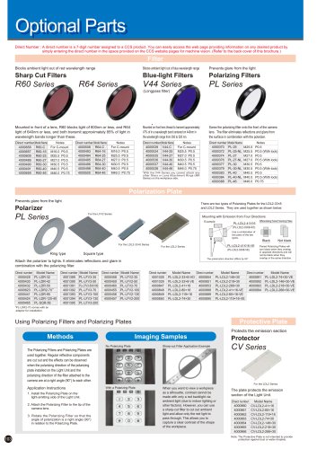
A freely adjustable light direction and angle allow these
models to handle a wide variety of applications.
Light Direction, Image A
Frame structure
Mounting tap holes
*The LDL2-33×8 Series provides only tap holes for installation.
A
Focus Angle Characteristics of
Wide and Narrow Types
B
A
Light Direction, Image B
There are two directional pattern selections: narrow, which focuses
the light into a beam, and wide (WD), which spreads the light out over
a broad area. This selection is available over the entire lineup.
Directional Characteristics of Narrow Model
Larger emission surface
Original lens
Relative irradiation strength
The two figures shown below
demonstrate how the illumination's
axis and angle can be changed to
yield completely different images.
This becomes an issue with
workpieces with glossy surfaces or
parallel grooves, for example. Bar
Lights are adjustable
allowing you to change
the light direction and
angle to obtain the optimal
B
image.
Installation can be achieved
with either frame mounting or
traditional mounting with tap
holes. You therefore have
the freedom to select the
installation method according
to your site environment.
40°
50°
60°
30°
20°
10°
1
-10° -20°
-30°
-40°
-50°
-60°
0.5
70°
-70°
80°
Mounting brackets are available for
four different illumination directions.
For further details, refer to page 105.
Illumination structure of LDL2-74×30
Camera
For the LDL2 Series
Lightweight, compact designs
lend themselves to installation
in tight equipment spaces.
This model
This model
(Wide Model)
21
30°
20°
0
Angle (deg.)
10°
1
0.5
-10° -20°
-30°
-40°
-50°
-60°
0.5
70°
-1
1
-70°
-80°
-0.5
0
0
Angle (deg.)
0.5
1
The LDL2-33×8, the smallest member
of the Series, helps you save space
(Narrow Model)
Object
40°
50°
60°
0
80°
For the LDL2-33×8 Series
LEDs are arranged at high-density on a single flat
circuit board and the work can be illuminated from
any angle as desired.
-0.5
Directional Characteristics of Wide Model
Larger emission surface
Relative irradiation strength
Image A is washed out because the light reflects straight back
from parallel metallic grooves. Image B shows the lettering
clearly because the light reflects out of the field of view,
leaving the background dark.
-80°
-1
*Only the wide directional pattern is
available.
Application Examples
Installation in tight equipment spaces is
also possible.
Supplementing other lighting is an other
possible application.