عضویت
عضویت  ورود اعضا
 راهنمای خرید


Data sheet - Regulasonde0 pages
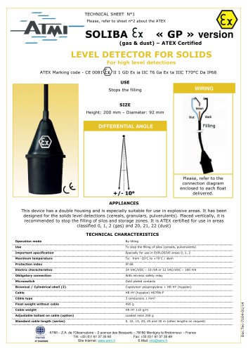
~ DATA SHEET
—REGULASONDE
ELECTRONIC REGULATOR
For automatic electronic level measurement
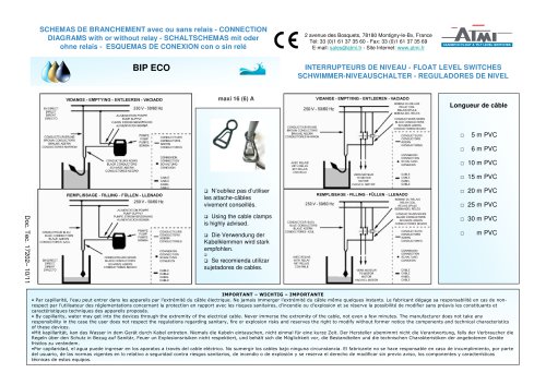
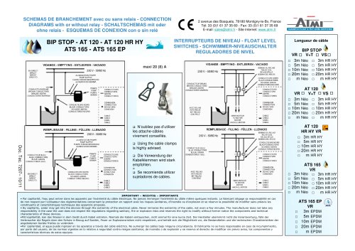
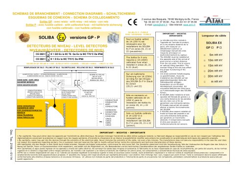
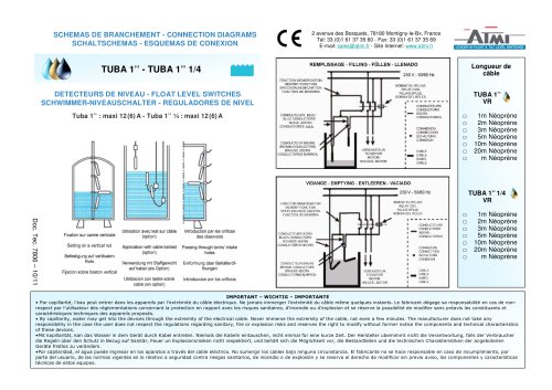
These automatic electronic regulators are mainly designed to start and to stop submerged or other types of
pumps and, in general to break electric circuits directly or via electrovalves, for example. Three probes are in-
stalled in the well or the tank and can be located up to 1,000 meters away from the control unit. This equipment
also features "water shortage" protection and automatic tank refill.
AT 5A and AT 5B
supply voltage: 220 V AC (110 V optional)
AT TOA and AT 10B
supply voltage:220 V AC
^=3
Regulasonde
Type AT 10/1
Vie AT tog
AT 20A
supply voltage:24,l 10,220 or 380 V AC
MAIN CHARACTERISTICS
• AC supply voltage (50/60 Hz)
- 110 or 220 V AC for types AT 5A & AT 5B
- 220 VAC for types AT 10A& AT 10B
- 24,110,220 or 380 V AC for type AT 20A
• Weight: 250 g
• Operating temperature : -10 to + 55 °C
• Power consumption : 1.5 VA
• Probe voltage : 10 V under 1 mA max. current
• Fluid resistance : 0 to 5.6 K ohms
• Maximum distance between low- and high-level probes: 2 m,
providing that drill 0 is under 100 mm
» Probe material (low, high and common) : AISI 316 stainless
steel
• PVC solid wire, 1 mm2 area
• Operating principle: Relay makes when all 3 probes are
submerged and breaks when the fluid level reaches the
lowest probe
• Direct motor start under 5A - 270 V possible (without relay)
• Tropicalized material
MOUNTING
• Types AT 5A & AT 5B: for mounting on octagonal plates
• Types AT 10A, AT 1 OB & AT 20A: for panel mounting or instal-
lation on DIN bars in a cabinet
• These 3 models can also be mounted on walls or any other
surface by means of 2 screws.
SENSITIVITY
• Types AT 5A, AT 1 OA & AT 20A standard sensitivity. Recom-
mended to control submerged pumps, because they operate
smoothly under high humidity and have outstanding operating
reliability. Distance between control unit and probes can cover
up to 1000 meters
• Types AT 5B & AT 10B high sensitivity. Recommended for use
in narrow drill holes where distance between high and low le-
vel probes is over 2 m, and for use in slightly conductive fluids
(organic solvents, hydrocarbons, food products, etc.)
• Operating conditions: fluid resistance up to 70 K ohms
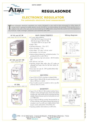
Wiring diagrams
DIRECT PUMP
CONTROL
Max 5A
270V
Position of contacts when the probes ate submerged
BE CAREFUL
new wire
connection
rl
' Position of contacts when the probes are submerged
i 17 16 12 11 10
NC C NA
DIRECT PUMP
CONTHOL
lax 5A
270V
4 3 □ / O 3
l/lll/l/l l/l
-241.
Ml
110 L Volts
220 J
3BO
Position of contacts when the probes are submerged
"