عضویت
عضویت  ورود اعضا
 راهنمای خرید


Series 1003 Specs0 pages

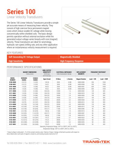
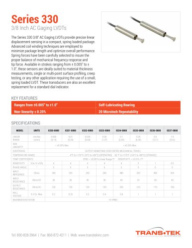
Model 1003
MODEL 1003
Transducer Indicator
Transducer Indicator
The Model 1003 Transducer Indicator provides complete
electronic support to AC and DC LVDT’s, or other DC powered
transducers. The AC version provides an appropriate excitation
voltage (at 3 or 7 KHz) for the LVDT and also demodulates the
output, providing not only a digital readout, but a continuous
analog output. This eliminates the need for a separate oscillator/
demodulator. The DC version contains a dual power supply for
transducers requiring both positive and negative excitation. Ideal
for use in the lab or in a high speed closed loop system, this
versatile indicator comes standard with a 5 digit L.E.D. readout
to provide maximum resolution.
SPECIFICATIONS
SUPPLY VOLTAGE TO TRANSDUCER
MAX. TRANSDUCER OUTPUT
ANALOG OUTPUT VOLTAGE1
FREQUENCY RESPONSE (nominal)
1.7 VRMS ±4% into 100 Ohm Min.
0.973 VRMS
Adjustable to ±5.0 VDC with LVDT
FS Output of .74 VRMS to .92 VRMS
300 Hz
NOISE AND RIPPLE
±15 VDC ±5%; up to 30 mA
±13.2 VDC
Adjustable to ±5.0 VDC with LVDT
FS Output of 2.9 VDC to 13.2 VDC
375 Hz
< 2 mVRMS
STABILITY
±0.002%
1
Notes: Impedance < 2 Ohm; can operate into 1000 Ohm Min. without distortion. Short circuit protected.
OPTIONS
RS232C
KEY FEATURES
RELAYS
Mode
• Panel Mount Indicator
• Supports AC and DC Transducers
Baud Rate
• Splashproof Front Panel
Half Duplex Transmit Only
1200 (Factory Set)
(600 to 19,200 available)
• 4 Independent Setpoints
DSR - Data Set Ready
DTR - Data Terminal Ready
DTX - Transmit Data Signal
Handshake
With RS232C
Without RS232C
Rating
Response Time
4 - N.O./ COM.
4 - N.O./ COM./ N.C.
250 VRMS @ 4 A Max.
30 VDC @ 3 A Max.
"on" approx. 8 msec.
"off" approx. 5 msec
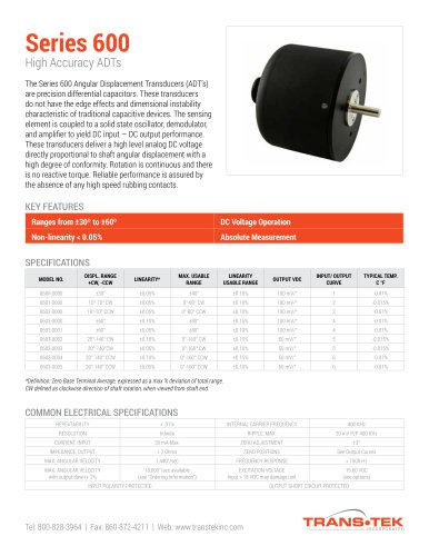
Calibrating the unit is accomplished via membrane switches on
the front panel, eliminating the need for internal trim pot
adjustment. The user can calibrate the unit by simply entering
the full scale endpoints, the zero position, and decimal point
location. This allows a readout in inches, degrees, or other
engineering units corresponding to the application. During the
calibration, there are 6 user defined setpoints: two high, two low,
and the high and low hysteresis points for the system. When the
specified tolerances are exceeded, indicator lights are illuminated,
providing a visual signal to the user. Optional relays, which
correspond to the distinct set points, will add another level of
Set Points
2 High; 2 Low
Hysteresis Points
1 High; 1 Low
automation to the user’s process. A tare function, which allows
the meter to be zeroed anywhere along the transducer’s travel, is
standard. This feature can be used to measure the deviation from
a standard within the working range of the sensor.
The Model 1003 features a continuous analog output for use as
an input to a control process or A/D converter. Optional RS232C
Serial output is offered for direct connection to PC based data
acquisition systems, eliminating the need for external signal
conditioning. All connectors necessary for indicator operation
are provided, as well as a complete instruction manual.
ORDERING INFORMATION
Model #
S-Number Description
INDICATOR SPECIFICATIONS
DIMENSIONS
INCHES (mm)
Case Size (H x W x L)
1.72 (44) x 3.56 (90) x 5.0 (127)
TEMPERATURE
Operating
+31°F to +131°F (0°C to +55°C)
Front Panel (H x W x L)
1.91 (49) x 3.80 (97) x 0.1 (3)
Storage
-40°F to +185°F (-40°C to +85°C)
Cut Out (H x W)
1.77 (45) x 3.62 (92)
Coefficient of Sensitivity
±0.006%/°F Typ.
Max. Panel Thickness
0.25 (6.35)
Coefficient of Zero
±2 LSD Max.
INPUT
DISPLAY
Supply Voltage
115 VRMS ±10%; 50/60 Hz
Accuracy
±0.01% Reading ±1 LSD
Once every 500 msec
Fax:
Web:
860-872-4211
www.transtekinc.com
Tel: 800-828-3964
860-872-8351
70
04C
34 in pb spreads
1 part in 20,000
Update
Tel: 800-828-3964
860-872-8351
5 Digit; 0.4” high
Resolution
0.05A
Current
Readout (Red LED)
(220 VRMS Optional)
20
04C
Fax:
Web:
860-872-4211
www.transtekinc.com
71
04C
4/30/04, 8:42 AM
04C
"