عضویت
عضویت  ورود اعضا
 راهنمای خرید


Rectangular sightglasss fitting0 pages

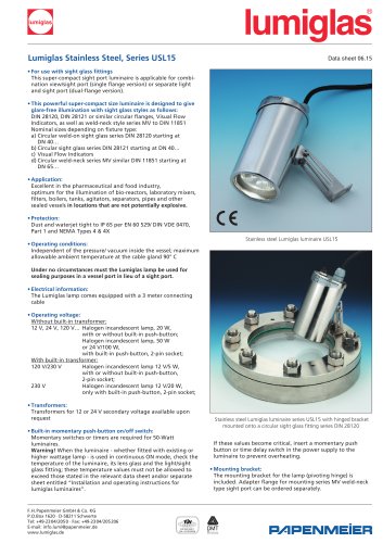
lumiglas
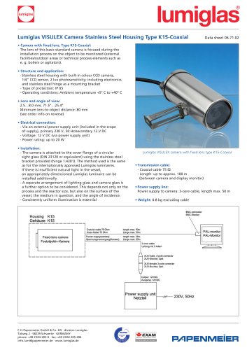
Rectangular Sightglass Fittings Data Sheet 01.20
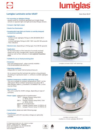
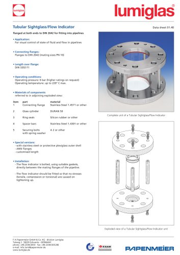
The base flange of the sightglass unit is welded into or onto the
vessel wall; the glass plate with gasket either side is firmly held in
place by bolted on cover flange.
• Application:
For viewing the internals of pipelines, containers, pressure vessels,
reactors, silos etc. used principally as a liquid level indicator
• Operating Pressure:
Pressure 16 bar
Vacuum
NB: Before putting the fitting into operation, the strength of
the cutout reinforcement in combination with the vessel wall
should be checked in accordance with TÜV leaflet B 9
(AD Merkblatt B 9).
• Operating Temperature:
100° C when using sodalime glass, DIN 8903
243° C when using borosilicate glass, DIN 7081
These temperatures refer to unprotected glass (i.e. without mica
protective sheet).
• Certification/Acceptance test:
If required by customer, and against additional charge, testing
and certification can be provided to DIN EN 10204 3.1/3.2
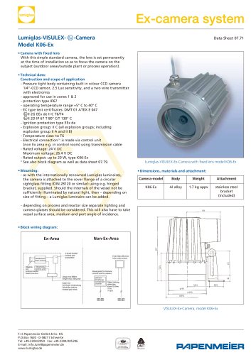
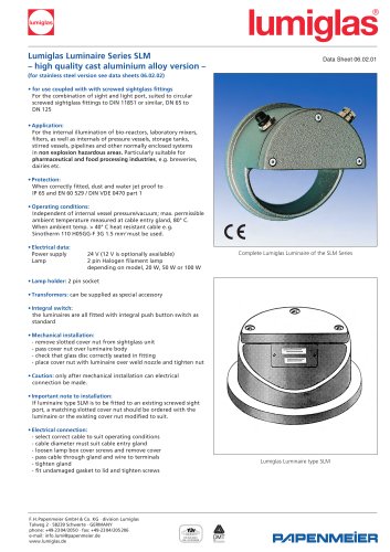
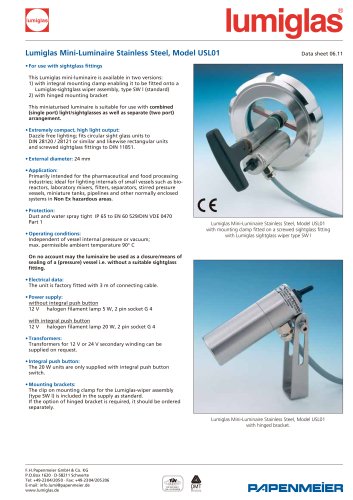
•Parts and available materials in explosion drawing on the right:
Items Parts name Material options
1 base frame carbon steel RSt 37-2;
stainless steel 1.4571, 316 Ti
or alternative
2 seal KLINGERSil C-4400; Neoprene;
PTFE or alternative
3 sightglass plate -soda lime glass: thermally
prestressed, DIN 8903, max 100° C
-borosilicate glass: thermally
prestressed, DIN 7081, max 243° C
4 cover frame carbon steel RSt 37-2;
stainless steel 1.4571, 316 Ti
or alternative
5 securing bolts carbon steel 5.6 or stainless
steel A2
• Assembly:
Prior to assembling check the base flange (1) to ensure that the
seating for the glass is flat and free from any distortion resulting
from welding into/onto the vessel wall. Any distortion or uneven
spots can lead to leakage or even breakage of the glass when
cover flange is tightened down.
After the base flange (1) is welded correctly, place glass (3)
gaskets (2) and cover frame (4) in the order shown in adjoining
illustration into the recess of base flange (1) and locate with bolts
(5) ensuring all is properly seated when bolts are handtight.
Progressively and carefully tighten down cover flange
commencing with bolts in middle of flange and working outwards
in crosswise alternating sequence (refer to sequence
numbers 1-14 in illustration.
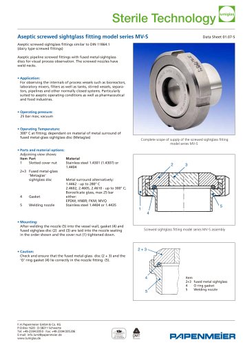
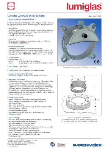
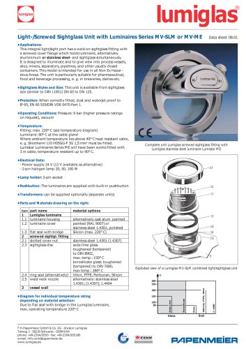
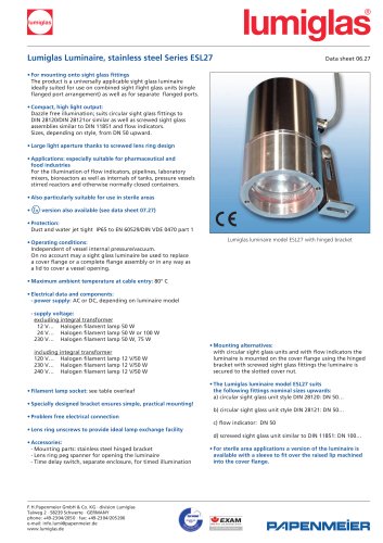
Complete assembly of a rectangular sightglass unit
Exploded view of a rectangular sightglass assembly
lumiglas®
1
3
7
14
5
9
11
2
6
10
12
4
8
13
EN ISO 9001
Q A: 041003296
F.H.Papenmeier GmbH & Co. KG · division Lumiglas
Talweg 2 · 58239 Schwerte · GERMANY
phone: +49-2304/2050 · fax: +49-2304/205206
e-mail: info.lumi@papenmeier.de
www.lumiglas.de