عضویت
عضویت  ورود اعضا
 راهنمای خرید


F311, F311 S0 pages
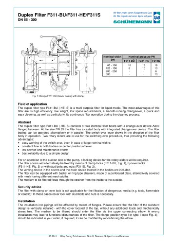
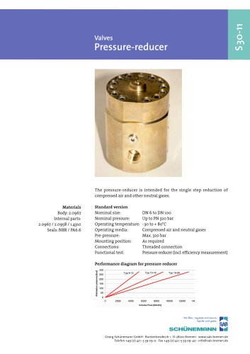
Duplex Filter F311-BU/F311-HE/F311S
Wir filtern, regeln, sichern Flüssigkeiten und Gase
We filter, regulate and secure liquids and gases
DN 65 - 300
Nominal width
DN
065 - 100
125 - 150
200 - 250
300
Nominal pressure PN
F311-BÜ
F311-HE
F311S
10
6
-
16
10
-
16
10
6
10
Fig. 1: Design F311-BU (Cover closing with clamp)
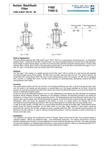
Field of application
The duplex filter type F311-BU (-HE, S) is a multi purpose filter for liquid media. The most advantages of this
filter are its high efficiency, low weight, low space requirements, a smooth-running changeover, a quick and
easy cleaning, as well as particularly, its continuous filter operation during the cleaning process.
Abstract
The duplex filter type F311-BU (-HE, S) consists of two identical filter bowls with a change-over device A300
flanged between. At the size DN 65 the filter has a casted body with integrated change-over device. The filter
bodies can be operated alternatively or in parallel. The switch-over lever shows in the direction of the filter
body in operation. Two rotary sliders are in use for the switching-over procedure, thus providing the following
advantages:
• easy working of the switch-over, even in case of large nominal widths
• constant flow to both bodies on center position of lever
• low service and maintenance efforts
• best reliability due to a simple design
For an operation at the suction side of the pump, a locking device for the rotary sliders will be required.
The filter covers will alternatively be fixed by means of clamp locks (F311-BU, Fig. 1), by lever locks
(F311-HE, Fig. 3) or with stud bolts and nuts (F311S, Fig. 2).
The venting device in the covers and the drain device located in the bodies are included.
The filter can be equipped with basket or ring type strainers, made of a perforated plate, alternatively covered
with mesh having different mesh widths.
The medium to be filtered flows through the strainer from the inside to the outside.
Security advice
The filter with clamp or lever lock is not applicable for the filtration of dangerous media (e.g. toxic, flammable
or caustic)! In these cases cover lock with stud bolts and nuts is necessary.
Installation
The installation into pipings will be effected by means of flanges. Please ensure that the filter of the standard
design is vertically installed - with the cover located at the top, without any additional loads and mechanically
stress free. The medium to be filtered should enter the filter via the upper connecting elbow. A wrong
installation may lead to functional disturbances of the filter. The flange position type I or type II (see Fig. 3) should be indicated in your order, if required, it can be modified by repositioning the elbow.
08.2011
© by Georg Schünemann GmbH, Bremen, Subject to modifications
"