عضویت
عضویت  ورود اعضا
 راهنمای خرید


Tubular Sightglass/Flow Indicator0 pages
lumiglas
Data sheet 01.40
lumiglas®
F.H.Papenmeier GmbH & Co. KG · division Lumiglas
Talweg 2 · 58239 Schwerte · GERMANY
phone: +49-2304/2050 · fax: +49-2304/205206
e-mail: info.lumi@papenmeier.de
www.lumiglas.de
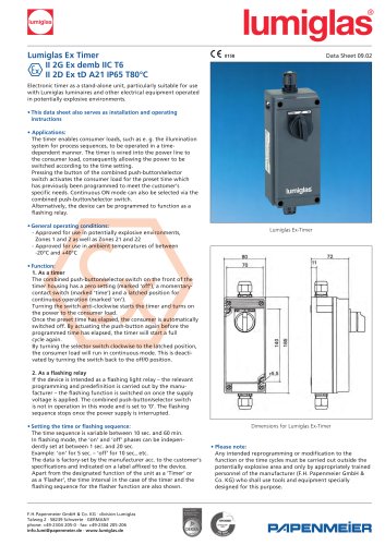
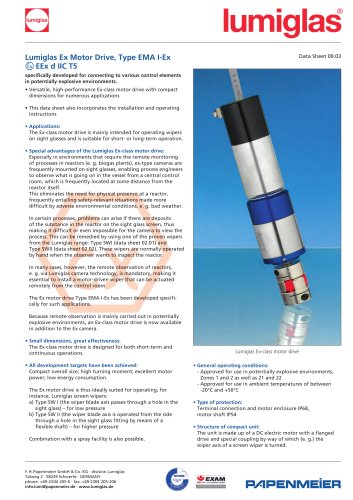
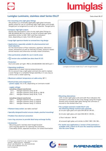
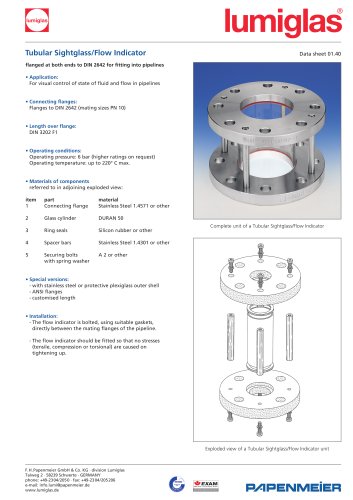
Exploded view of a Tubular Sightglass/Flow Indicator unit
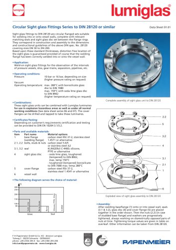
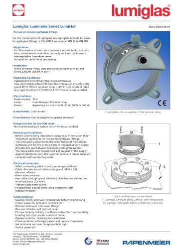
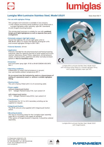
Complete unit of a Tubular Sightglass/Flow Indicator
Tubular Sightglass/Flow Indicator
flanged at both ends to DIN 2642 for fitting into pipelines
• Application:
For visual control of state of fluid and flow in pipelines
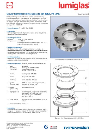
• Connecting flanges:
Flanges to DIN 2642 (mating sizes PN 10)
• Length over flange:
DIN 3202 F1
• Operating conditions:
Operating pressure: 6 bar (higher ratings on request)
Operating temperature: up to 220° C max.
• Materials of components
referred to in adjoining exploded view:
item part material
1 Connecting flange Stainless Steel 1.4571 or other
2 Glass cylinder DURAN 50
3 Ring seals Silicon rubber or other
4 Spacer bars Stainless Steel 1.4301 or other
5 Securing bolts A 2 or other
with spring washer
• Special versions:
- with stainless steel or protective plexiglass outer shell
- ANSI flanges
- customised length
• Installation:
- The flow indicator is bolted, using suitable gaskets,
directly between the mating flanges of the pipeline.
- The flow indicator should be fitted so that no stresses
(tensile, compression or torsional) are caused on
tightening up.