عضویت
عضویت  ورود اعضا
 راهنمای خرید


VeSys0 pages
Electrical Systems Design and
Wire Harness Engineering
D A T A S H E E T
www.mentor.com/vesys
VeSys 2.0 Design Highlights
• Rapid circuit design with intuitive
user interface
• Simulation validates the electrical
design as it is created
• Simulation highlights short circuits,
volt-drop, fusing and wire
sizing errors
• Automatic cross-referencing for
multi-sheet parts and wires
• Customizable drawing styles
• Automated report generation
• Built-in intelligent libraries for
components, symbols and simulation
models
• Integration with MCAD systems
for 3D harness routing and wire
length back-annotation
• Embedded Test Drive tutorial
included
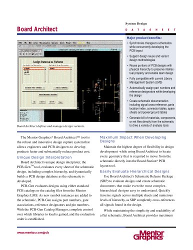
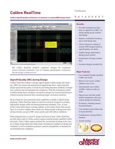
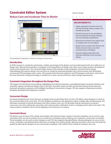
VeSys® 2.0 Design
Intuitive
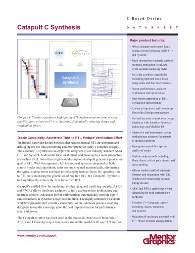
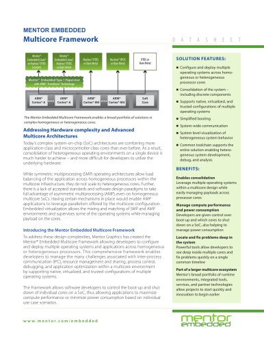
VeSys 2.0 Design provides a graphical environment for creating wiring diagrams.
Full electrical design authoring is made easy via an intuitive user interface and
electrically intelligent symbols. Built-in electrical intelligence automates many
design tasks. For example, splices are automatically created when wires are joined
and cross-references are automatically created when wires cross between sheets.
Furthermore, all entities have context sensitive menus giving the user the modification
options appropriate for each different type of component. These and many
other facilities make circuit editing a quick and simple.
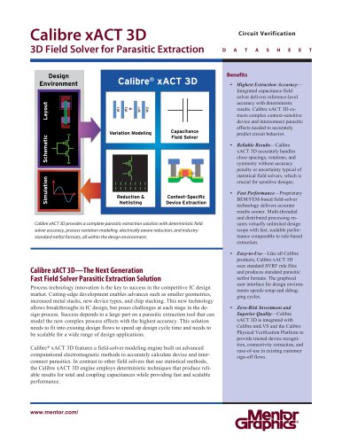
Powerful
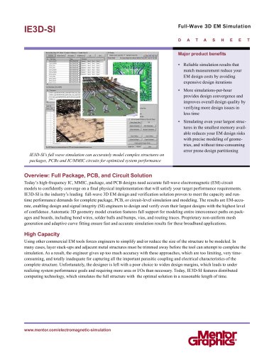
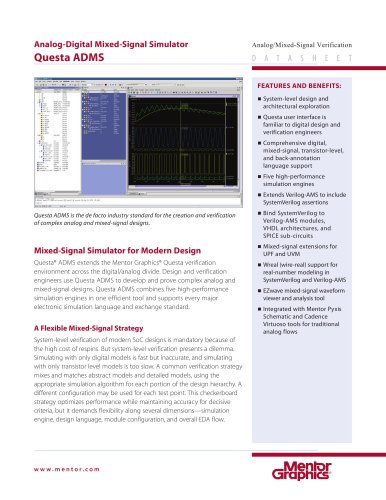
Built-in simulation helps designers to check and validate the design, as it is created,
helping to find errors fast and early in the design phase. Simulation shows
voltages and currents, highlighting problem areas such as short circuits and validating
wire and fuse sizing.
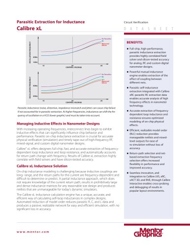
Designs can be split into multiple sheets with automated cross-referencing and
hyperlinks, helping users navigate the design. Diagram appearance – line weights,
fonts, colors, symbols, borders, etc is fully customizable.
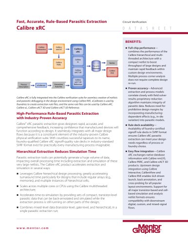
Libraries are provided for components, symbols and analysis models and these can
be shared and exchanged with other companies.
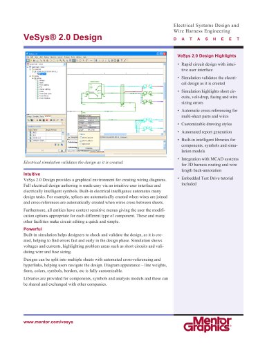
Electrical simulation validates the design as it is created.