عضویت
عضویت  ورود اعضا
 راهنمای خرید


TransLayoutâ„¢0 pages
www.mentor.com/harness
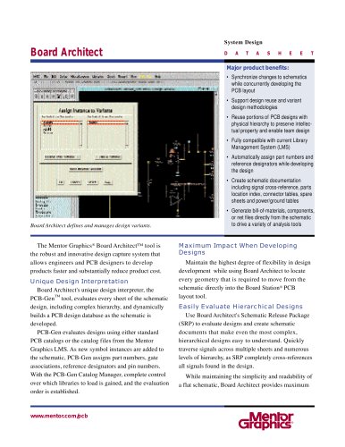
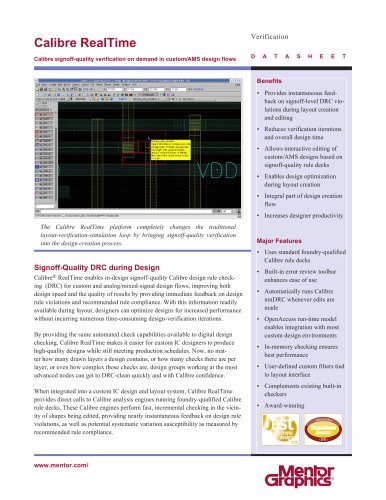
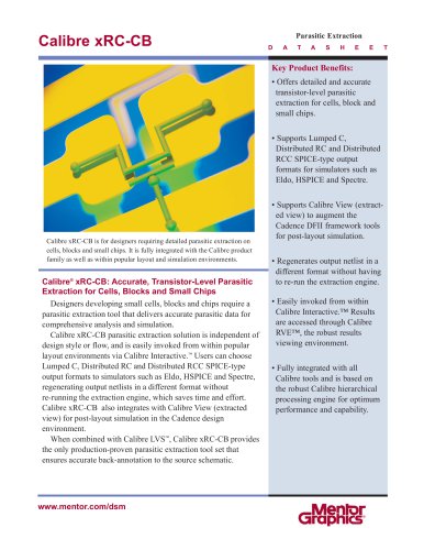
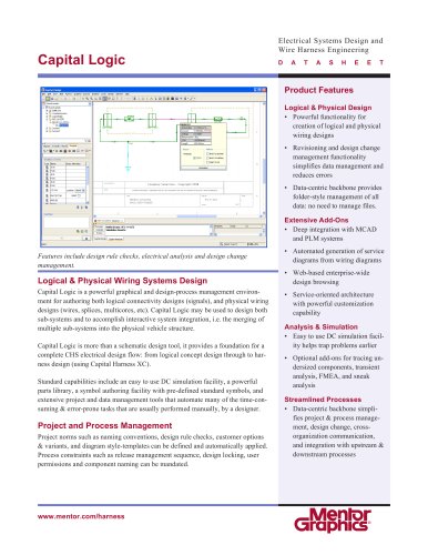
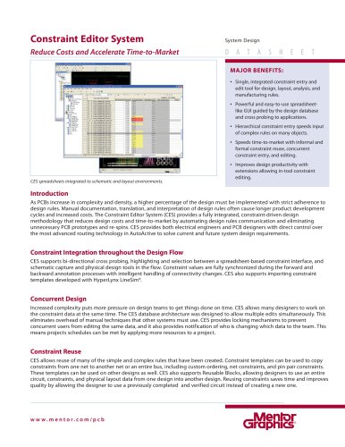
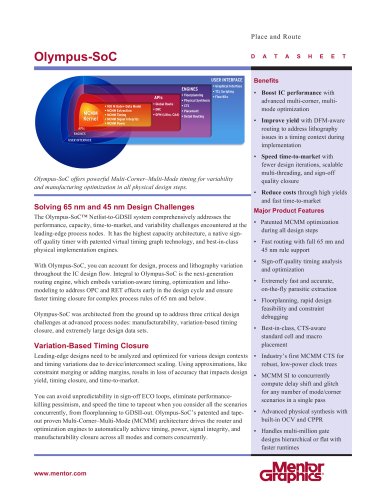
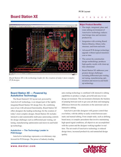
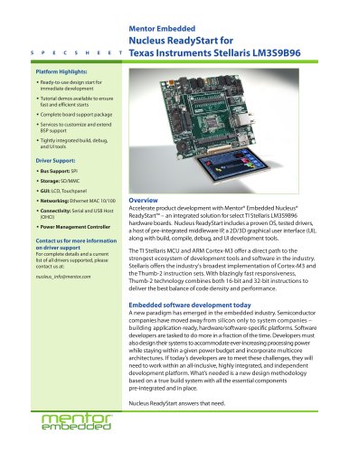
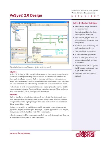
TransLayoutTM provides a design environment for complex systems from
concept through to manufacturing support. Early in the design process,
system and electrical engineers explore design alternatives for wire
harness and cable systems and assess their impact on manufacturing
cost and physical space requirements.
TransLayout
Wire Harness and Cable Design Using Interconnect Synthesis
Target Market
The transportation (automobiles, trucks,
trains), aerospace (planes, satellites), telecom,
semiconductor equipment, and industrial
machinery industries are experiencing an
increase in the electrical content of their
products. TransLayout enables design teams
to plan the electrical distribution system
within a simplified view of the physical
package and estimate manufacturing costs as
well as the complete development of the
physical interconnect of a system.
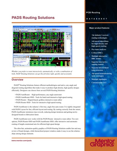
Design Scenario
Logical schematics are created that capture the
equipment, connectors, and pins that are
electrically connected within a system. Multiple
schematics may be configured together to
define the electrical distribution system.
The TC2TL utility will generate a netlist and
may be used to automatically generate
module symbols. A module symbol will
have pins that represent the associated
module side connectors.
A symbol representing the physical outline
with scaled dimensions of the mechanical
package may be placed within TransLayout
to provide the context for the design.
After importing a netlist, the user will place
either customized or automatically generated
module symbols within the physical outline.
Selecting signals highlights electrically
connected modules.
The user may simply draw conduit segments
between electrically connected modules to
create wire routing channels. TransLayout
may then be used to automatically synthesize
wires and splices through the routed channels.
Synthesizing Electrical Signals to
Physical Wires and Splices
The autorouter is used to synthesize wires
and splices from electrical signals by
adhering to electrical and manufacturing
design rules. Design rules are specified as
router cost values or router modes.
Examples of router cost values include
maximum number of wires per splice or
multi-termination, cost per unit length of a
wire, and minimum distance between splices
or between a splice and a take-out.
Autorouter modes may be used to allow or
disallow multiple wires terminating on
common pins or prioritizing router
performance over design iteration time.
The router will automatically assign the wire
gauge for a signal. It may also be used to
optimize the location of splices.
The autorouter will optimize the total wire
cost while satisfying electrical and
manufacturing design rules. The factors
contributing to total wire costs include base
wire, wire length, and the number of jumpers,
splices, and multi-terms. Total wire costs,
wire cut lengths, and bundle diameters are
automatically calculated.