عضویت
عضویت  ورود اعضا
 راهنمای خرید


LSR7805 Series0 pages
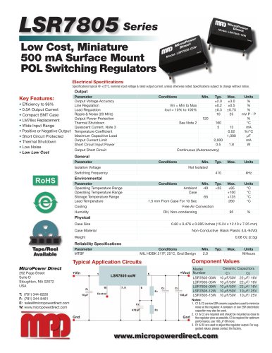
LSR7805 Datasheet table.main {} tr.row {} td.cell {} div.block {} div.paragraph {} .font0 { font:4.80pt "Arial", sans-serif; } .font1 { font:6.00pt "Arial", sans-serif; } .font2 { font:8.00pt "Arial", sans-serif; } .font3 { font:10.00pt "Arial", sans-serif; } .font4 { font:11.00pt "Arial", sans-serif; } .font5 { font:15.00pt "Arial", sans-serif; } .font6 { font:16.00pt "Arial", sans-serif; } .font7 { font:24.00pt "Arial", sans-serif; } .font8 { font:26.00pt "Arial", sans-serif; } .font9 { font:47.00pt "Arial", sans-serif; } LSR7805 Sries Low Cost, Miniature 500 mA Surface Mount POL Switching Regulators Electrical Spcifications Sp驩cifications typical @ +25°C, nominal input voltage & rated output current, unless otherwise noted. Spcifications subject to change without notice. Output Key Features: Efficiency to 96% 镕 0.5A Output Current Compact SMT Case Օ LM78xx Replacement Wide Input Range Օ Positive or Negative Output Short Circuit Protected Օ Thermal Shutdown Low Noise Օ Low Low Cost Conditions Min. Typ. Max. Units Output Voltage Accuracy ±2.0 ±3.0 % Line Regulation Vin = Min to Max ±0.2 ±0.5 % Load Regulation Iout = 10% to 100% ±0.3 ±0.75 % Ripple & Noise (20 MHz) 10 25 mV P - P Output Power Protection 120 % Thermal Shutdown See Note 2 160 °C Quiescent Current, Note 3 5 13 mA Temperature Coefficient 0.02 %/°C Maximum Capacitive Load 1,000 PF Output Current Limit 2,000 mA Short Circuit Input Power 0.5 1.8 W Output Short Circuit Continuous (Autorecovery) General Parameter Conditions Min. Typ. Max. Units Isolation Voltage Not Isolated Switching Frequency 410 kHz Environmental Parameter Conditions Min. Typ. Max. Units Operating Temperature Range Ambient -40 +25 +85 °C Operating Temperature Range Case +100 °C Storage Temperature Range -55 +125 °C Lead Temperature 1.5 mm From Case For 10 Sec 260 °C Cooling Free Air Convection Humidity RH, Non-condensing 95 % RoHS Physical Case Size 0.60 x 0.476 x 0.285 Inches (15.24 x 12.10 x 7.25 mm) Case Material Non-Conductive Black Plastic (UL-94V0) Weight 0.08 Oz (2.3g) Reliability Specifications Tape/Reel Available Parameter Conditions Min. Typ. Max. Units MTBF MIL HDBK 217F, 25°C, Gnd Benign 2.0 MHours Typical Application Circuits Component Values MicroPower Direct 292 Page Street Suite D Stoughton, MA 02072 USA T: (781) 344-8226 F: (781) 344-8481 E: sales@micropowerdirect.com W: www.micropowerdirect.com Model Ceramic Capacitors Number C1 C2 LSR7805-03W 10 PF/50V 22 PF/ 16V LSR7805-05W 10 PF/50V 22 PF/ 16V LSR7805-09W 10 PF/50V 22 PF/ 16V LSR7805-12W 10 PF/50V 10 PF/ 25V LSR7805-15W 10 PF/50V 10 PF/ 25V Notes: 1. C1 & C2 are low ESR ceramic capacitors used to minimize noise at the regulator. A tantalum or low ESR electrolytic capacitor may also be used. 2. C1 & C2 are required and should be mounted as close to the regulator pins as possible. C3 is required for optimum performance, use 100 |jF OR more. 3. R1 & R2 are used to adjust the regulator output. For sug-gested values, please contact the factory. www.micropowerdirect.com
"