عضویت
عضویت  ورود اعضا
 راهنمای خرید


Oil Reservoirs0 pages
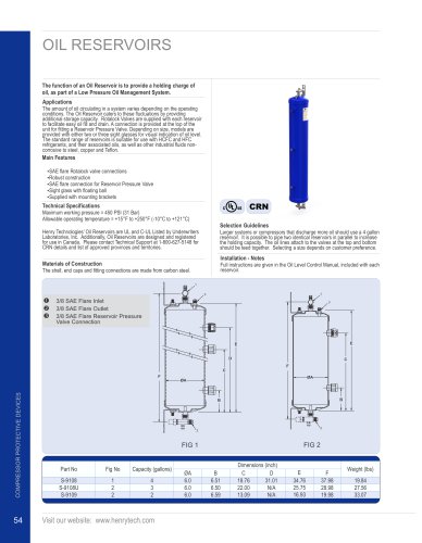
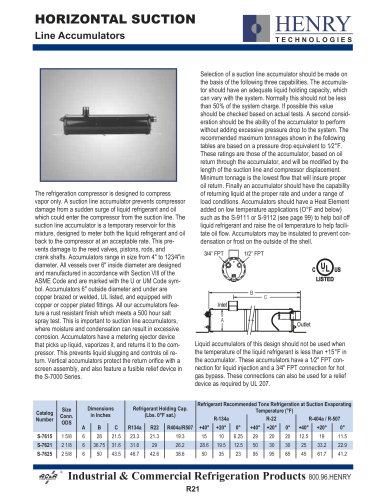
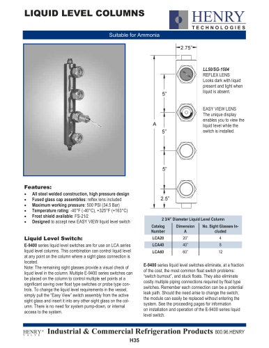
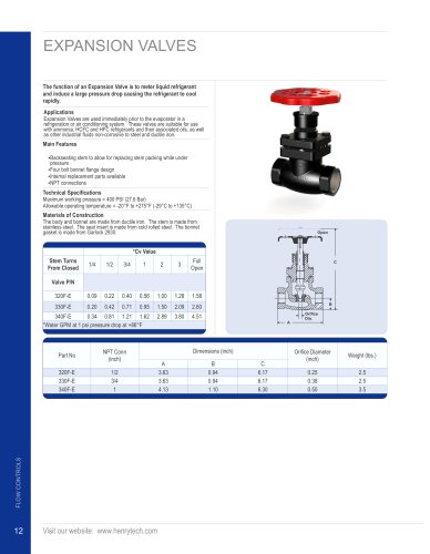
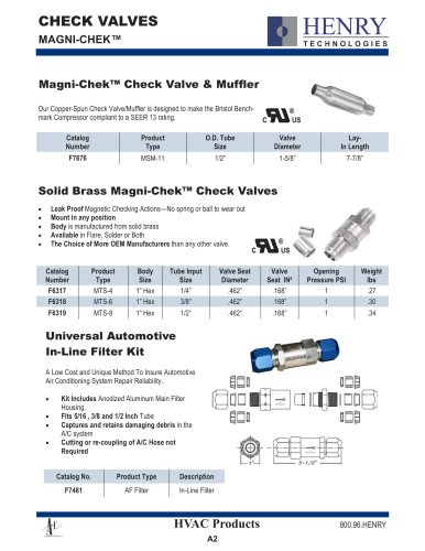
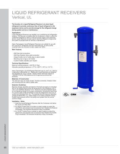
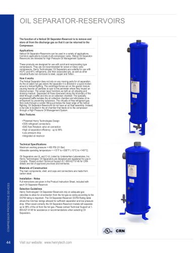
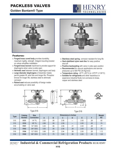
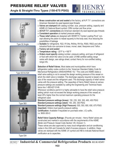
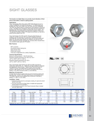
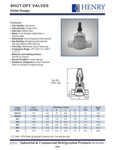
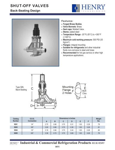
OIL RESERVOIRS
The function of an Oil Reservoir is to provide a holding charge of
oil, as part of a Low Pressure Oil Management System.
Applications
The amount of oil circulating in a system varies depending on the operating
conditions. The Oil Reservoir caters to these fluctuations by providing
additional storage capacity. Rotalock Valves are supplied with each reservoir
to facilitate easy oil fill and drain. A connection is provided at the top of the
unit for fitting a Reservoir Pressure Valve. Depending on size, models are
provided with either two or three sight glasses for visual indication of oil level.
The standard range of reservoirs is suitable for use with HCFC and HFC
refrigerants, and their associated oils, as well as other industrial fluids noncorrosive to steel, copper and Teflon.
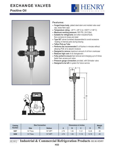
Main Features
SAE flare Rotalock valve connections
Ÿ
Robust construction
Ÿ
SAE flare connection for Reservoir Pressure Valve
Ÿ
Sight glass with floating ball
Ÿ
Supplied with mounting brackets
Ÿ
Technical Specifications
CRN
Maximum working pressure = 450 PSI (31 Bar)
Allowable operating temperature = +15°F to +250°F (-10°C to +121°C)
Selection Guidelines
Henry Technologies’ Oil Reservoirs are UL and C-UL Listed by Underwriters
Laboratories, Inc. Additionally, Oil Reservoirs are designed and registered
for use in Canada. Please contact Technical Support at 1-800-627-5148 for
CRN details and list of approved provinces and territories.
Larger systems or compressors that discharge more oil should use a 4 gallon
reservoir. It is possible to pipe two identical reservoirs in parallel to increase
the holding capacity. The oil lines attach to the valves at the top and bottom
should be teed together. Selecting a size depends on customer preference.
Installation - Notes
Materials of Construction
Full instructions are given in the Oil Level Control Manual, included with each
reservoir.
The shell, end caps and fitting connections are made from carbon steel.
1
1
3
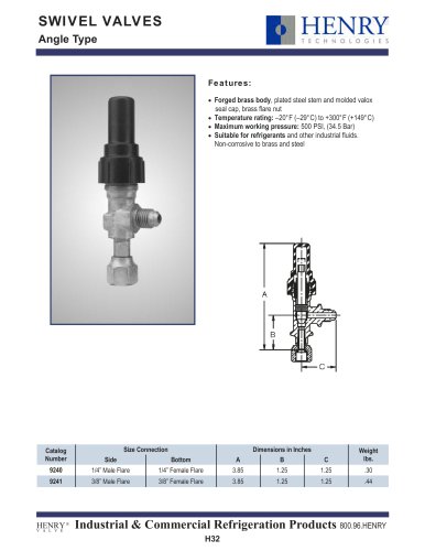
Π3/8 SAE Flare Inlet
3/8 SAE Flare Outlet
Ž 3/8 SAE Flare Reservoir Pressure
3
Valve Connection
E
E
D
C
F
C
F
ØA
COMPRESSOR PROTECTIVE DEVICES
ØA
54
B
B
2
2
FIG 2
FIG 1
Part No
Fig No
Capacity (gallons)
S-9108
S-9108U
S-9109
1
2
2
4
3
2
Visit our website: www.henrytech.com
ØA
6.0
6.0
6.0
B
6.51
6.50
6.59
Dimensions (inch)
D
C
18.76
31.01
22.00
N/A
13.09
N/A
E
34.76
25.75
16.93
F
37.98
28.98
19.98
Weight (lbs)
19.84
27.56
33.07