عضویت
عضویت  ورود اعضا
 راهنمای خرید


By-Pass Valve0 pages

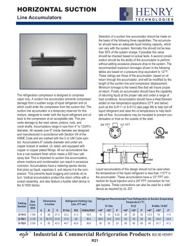
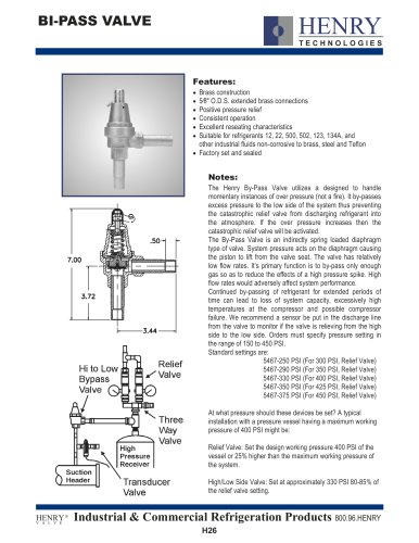
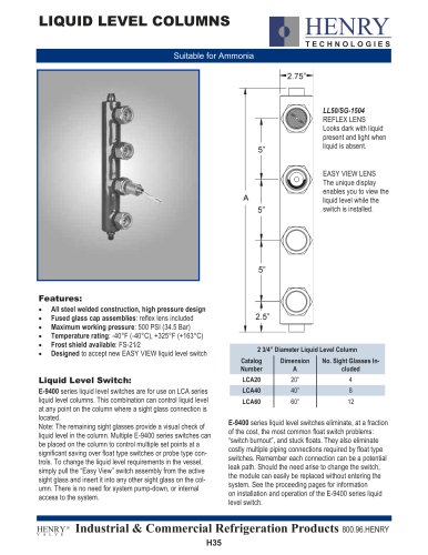
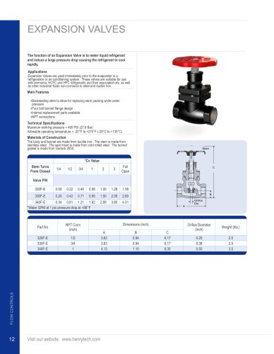
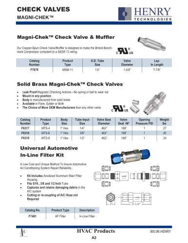
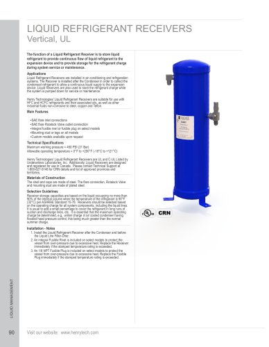
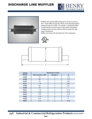
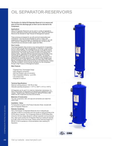
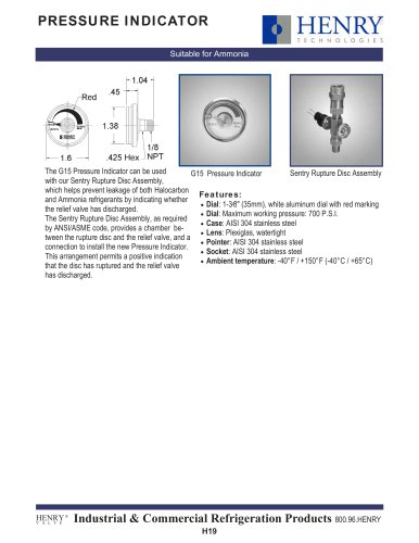
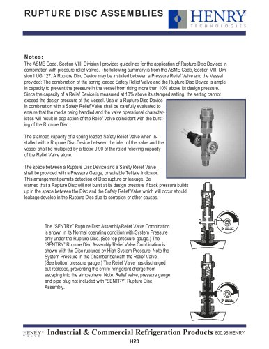
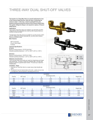
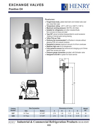
BY-PASS VALVES
The function of a By-Pass Valve is to handle momentary instances of
over pressure (not due to fire) to prevent Pressure Relief Valve
discharge.
Applications
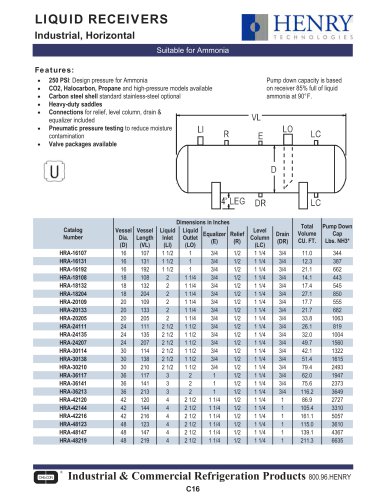
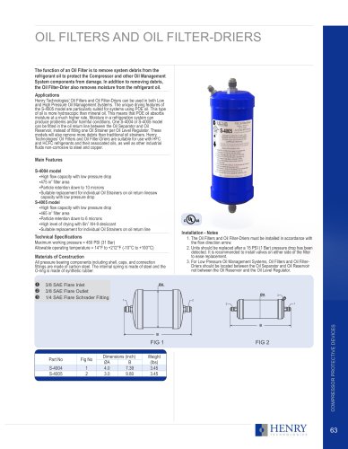
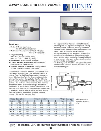
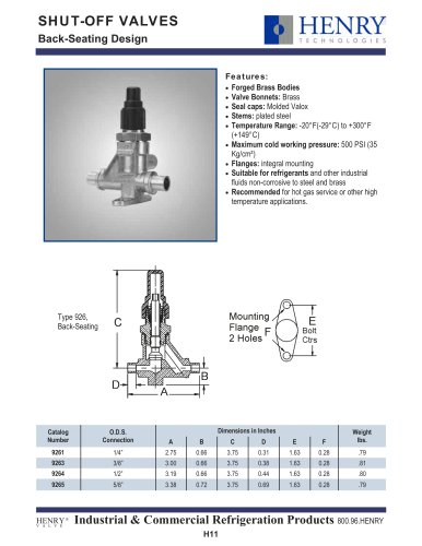
The Henry Technologies’ 5467 By-Pass Valve is positioned between the
pressure vessel and the Three-Way Valve before the Pressure Relief Valve
as shown in Figure 2 below. In the event of a high pressure spike, the valve
bypasses excess pressure to the low side of the system thus preventing the
Pressure Relief Valve from discharging refrigerant into the atmosphere. If
the over pressure increases then the Pressure Relief Valve will be activated.
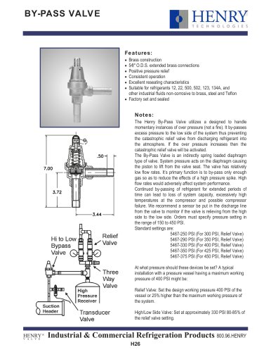
The valve is designed to bypass only enough gas to reduce the effects of
high pressure spikes. The valve has relatively low flow rates, thus high flow
rates would adversely affect system performance. Continuous bypassing of
refrigerant for extended periods of time can lead to loss of system capacity,
excessively high compressor temperatures, and possible compressor failure.
We recommend a sensor be put in the By-Pass Valve discharge line to
monitor if the valve is relieving from high to low side. All By-Pass Valves are
suitable for use with HFC and HCFC refrigerants and their associated oils, as
well as other industrial fluids non-corrosive to brass, steel, copper and Teflon.
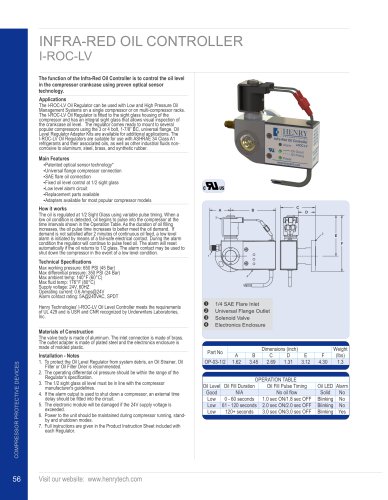
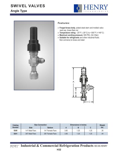
Main Features
Ÿ
Brass construction
Ÿ
Extended ODS connections
Ÿ
Positive pressure relief during high pressure spikes
Ÿ
Consistent operation and reseating
Ÿ
Flow direction arrow
Technical Specifications
Set pressure range: 150 to 450 PSI
Standard set pressures: 250, 290, 330, 350 and 375 PSI
Allowable operating temperature: -20°F to +200°F (-29°C to +93°C)
Selection Guidelines
Henry Technologies By-Pass Valves are to be set approximately 80-85% of
relief valve setting. See the Relief Valve Selection Guidelines located in this
catalog for more information.
ΠInlet
Outlet
Relief
Valve
Hi to Low
By-Pass
Valve
D
1
Three
Way
Valve
A
High
Pressure
Receiver
B
Suction
Header
Transducer
Valve
2
C
FIG 2
SAFETY DEVICES
FIG 1
30
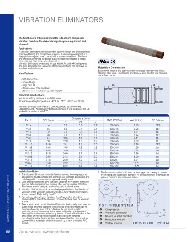
Part No
5467-250
5467-290
5467-330
5467-350
5467-375
By-Pass Valve Setting
(PSI)
250
290
330
350
375
Capacity
(#Air/Min)
3.5
4.0
4.5
4.8
5.1
Visit our website: www.henrytech.com
Relief Valve Setting
(PSI)
300
350
400
425
450
ODS
(Inch)
5/8
5/8
5/8
5/8
5/8
A
7.43
7.43
7.43
7.43
7.43
Dimensions (inch)
B
C
3.60
3.88
3.60
3.88
3.60
3.88
3.60
3.88
3.60
3.88
D
0.69
0.69
0.69
0.69
0.69
Weight
(lbs)
2.60
2.60
2.60
2.60
2.60