عضویت
عضویت  ورود اعضا
 راهنمای خرید


accummulator0 pages
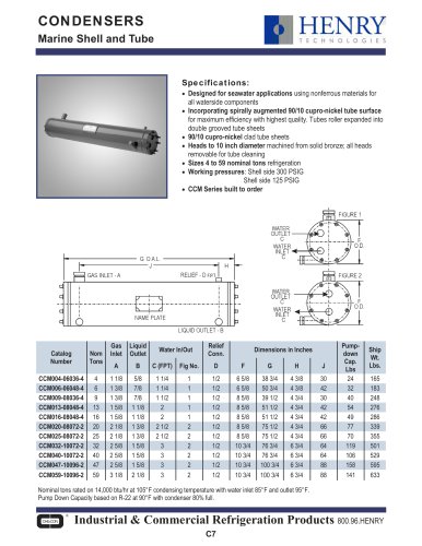
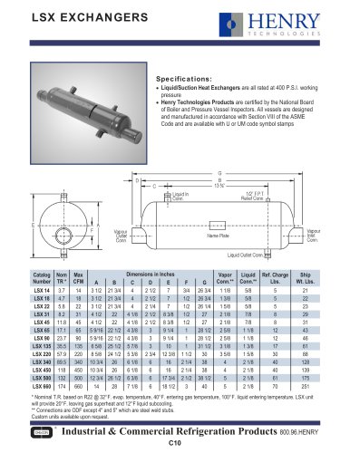
HORIZONTAL SUCTION
nnnnLine Accumulators
nnnnHENRY
nnnnTECHNOLOGIES
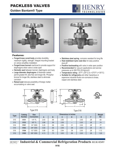
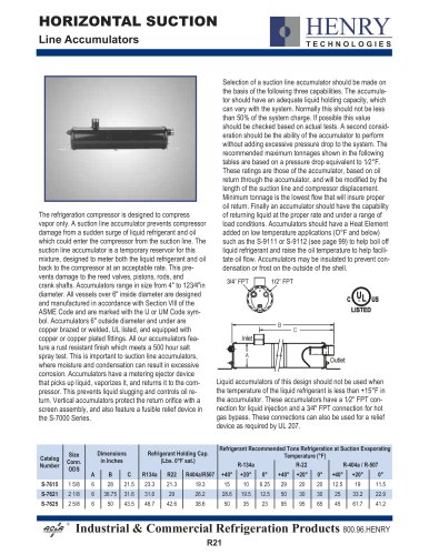
nnnnThe refrigeration compressor is designed to compress
nnnnvapor only. A suction line accumulator prevents compressor
nnnndamage from a sudden surge of liquid refrigerant and oil
nnnnwhich could enter the compressor from the suction line. The
nnnnsuction line accumulator is a temporary reservoir for this
nnnnmixture, designed to meter both the liquid refrigerant and oil
nnnnback to the compressor at an acceptable rate. This pre-
nnnnvents damage to the reed valves, pistons, rods, and
nnnncrank shafts. Accumulators range in size from 4" to 123^+"in
nnnndiameter. All vessels over 6" inside diameter are designed
nnnnand manufactured in accordance with Section VIII of the
nnnnASME Code and are marked with the U or UM Code sym-
nnnnbol. Accumulators 6" outside diameter and under are
nnnncopper brazed or welded, UL listed, and equipped with
nnnncopper or copper plated fittings. All our accumulators fea-
nnnnture a rust resistant finish which meets a 500 hour salt
nnnnspray test. This is important to suction line accumulators,
nnnnwhere moisture and condensation can result in excessive
nnnncorrosion. Accumulators have a metering ejector device
nnnnthat picks up liquid, vaporizes it, and returns it to the com-
nnnnpressor. This prevents liquid slugging and controls oil re-
nnnnturn. Vertical accumulators protect the return orifice with a
nnnnscreen assembly, and also feature a fusible relief device in
nnnnthe S-7000 Series.
nnnnSelection of a suction line accumulator should be made on
nnnnthe basis of the following three capabilities. The accumula-
nnnntor should have an adequate liquid holding capacity, which
nnnncan vary with the system. Normally this should not be less
nnnnthan 50% of the system charge. If possible this value
nnnnshould be checked based on actual tests. A second consid-
nnnneration should be the ability of the accumulator to perform
nnnnwithout adding excessive pressure drop to the system. The
nnnnrecommended maximum tonnages shown in the following
nnnntables are based on a pressure drop equivalent to 1/2°F.
nnnnThese ratings are those of the accumulator, based on oil
nnnnreturn through the accumulator, and will be modified by the
nnnnlength of the suction line and compressor displacement.
nnnnMinimum tonnage Is the lowest flow that will insure proper
nnnnoil return. Finally an accumulator should have the capability
nnnnof returning liquid at the proper rate and under a range of
nnnnload conditions. Accumulators should have a Heat Element
nnnnadded on low temperature applications (0°F and below)
nnnnsuch as the S-9111 or S-9112 (see page 99) to help boil off
nnnnliquid refrigerant and raise the oil temperature to help facili-
nnnntate oil flow. Accumulators may be insulated to prevent con-
nnnndensation or frost on the outside of the shell.
nnnn3/4:l FPT
nnnn1/2" FPT
nnnnLiquid accumulators of this design should not be used when
nnnnthe temperature of the liquid refrigerant Is less than +15°F In
nnnnthe accumulator. These accumulators have a 1/2" FPT con-
nnnnnection for liquid Injection and a y4" FPT connection for hot
nnnngas bypass. These connections can also be used for a relief
nnnndevice as required by UL 207.
nnnnCatalog Number | Size Conn. ODS | D A | imensic n Inche B | ns s C | Refrij R134a | jerant He (Lbs. 0°F R22 | Iding Cap. sat.) R404a/R507 | Refrige +40° | rant Re R-134a +20° | comme 0° | ided To Terr +40° | ns Refr iperatu R-22 +20° | igeratic re (°F) 0° | n at Su R +40° | ction Eve -404a/R +20° | porating 507 0° |
S-7615 | 1 5/8 | 6 | 28 | 21.5 | 23.3 | 21.3 | 19.3 | 15 | 10 | 6.25 | 29 | 20 | 20 | 12.5 | 19 | 11.5 |
S-7621 | 2 1/8 | 6 | 36.75 | 31.6 | 31.6 | 29 | 26.2 | 28.6 | 19.5 | 12.5 | 50 | 30 | 30 | 25 | 33.2 | 22.9 |
S-7625 | 2 5/8 | 6 | 50 | 43.5 | 46.7 | 42.6 | 38.6 | 50 | 35 | 23 | 95 | 95 | 65 | 45 | 61.7 | 41.2 |
COMPONENTS
nnnnIndustrial & Commercial Refrigeration Products 800.96.HENRY
nnnnR21
"