عضویت
عضویت  ورود اعضا
 راهنمای خرید


Valve, 3-Way0 pages
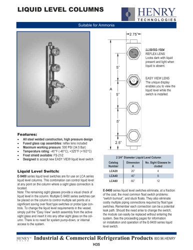
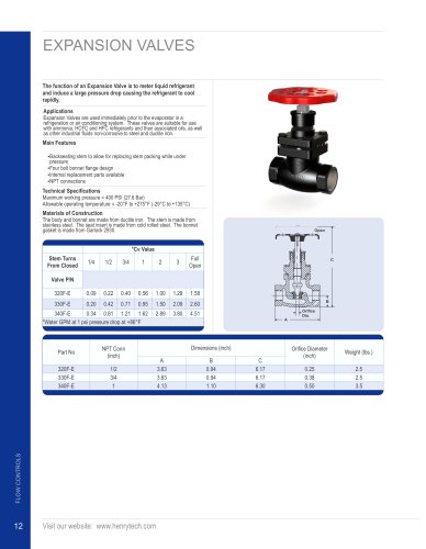
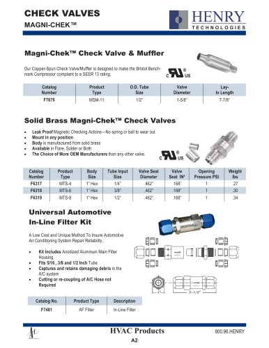
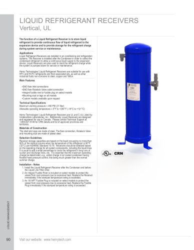
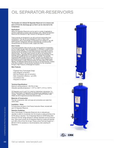
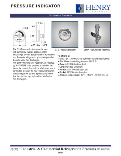
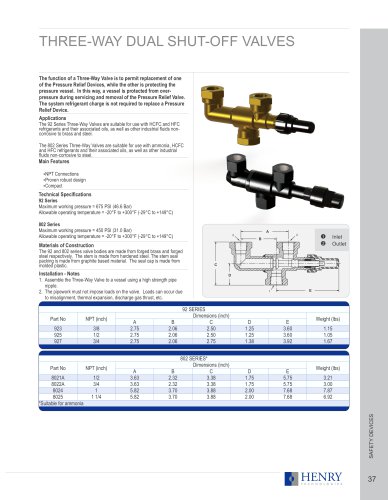
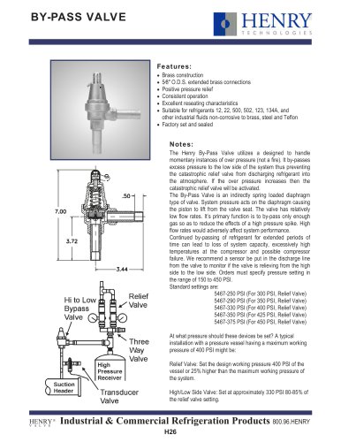
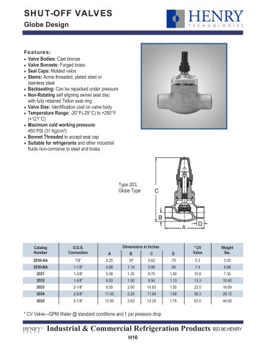
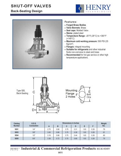
3-WAY DUAL SHUT-OFF VALVES
Features:
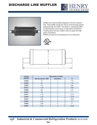
The design of this Three-Way Valve provides full discharge
area through the valve regardless of stem position, assuring
maximum protection. Furthermore, this design provides for
convenient parallel mounting of the two relief valves and fulfills
the requirement set forth in the ANSI/ASHRAE 15.
“No stop valve shall be located between any automatic pressure relief device or fusible plug and the part or parts of the
system protected thereby, except when the parallel relief devices are so arranged that only one can be rendered inoperative
at a time for test or repair purposes.”
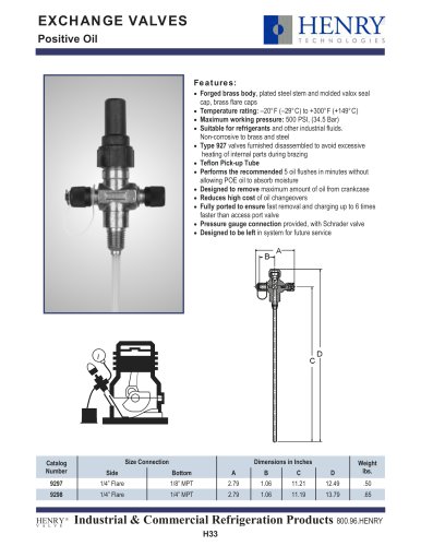
Two three-way valves, installed in a drier bypass arrangement,
permit installation or removal of service drier without air, dirt,
or moisture entering line.
Bodies: 92 Series: forged brass;
802 series: forged steel; painted
Maximum working pressure: 450 PSI (31.0 Bar) Steel
675 PSI (46.6 Bar) Brass
Temperature rating:
Steel -20°F (-29°C) to +300°F (+149°C)
Brass –40°F (-40°C) to +300°F (+149°C)
Recommended for use with relief valve types
92 series is suitable for refrigerants and other industrial
fluids non-corrosive to steel and brass
802 Series is suitable for refrigerants including ammonia
and other industrial fluids non-corrosive to steel
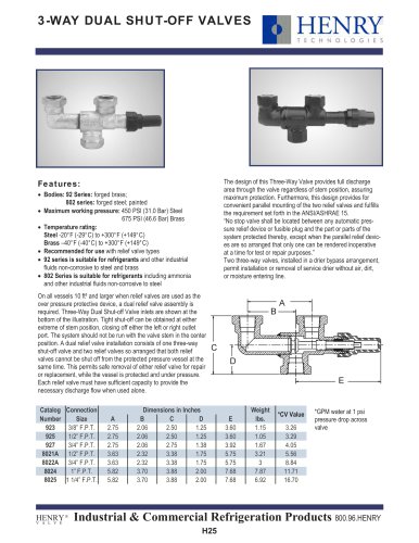
On all vessels 10 ft³ and larger when relief valves are used as the
over pressure protective device, a dual relief valve assembly is
required. Three-Way Dual Shut-off Valve inlets are shown at the
bottom of the illustration. Tight shut-off can be obtained at either
extreme of stem position, closing off either the left or right outlet
port. The system should not be run with the valve stem in the center
position. A dual relief valve installation consists of one three-way
shut-off valve and two relief valves so arranged that both relief
valves cannot be shut off from the protected pressure vessel at the
same time. This permits safe removal of either relief valve for repair
or replacement, while the vessel is protected and under pressure.
Each relief valve must have sufficient capacity to provide the
necessary discharge flow when used alone.
Catalog Connection
Number
Size
923
3/8” F.P.T.
925
1/2” F.P.T.
927
3/4” F.P.T.
8021A 1/2” F.P.T.
8022A 3/4” F.P.T.
8024
1” F.P.T.
8025 1 1/4” F.P.T.
HENRY ®
V A L V E
A
2.75
2.75
2.75
3.63
3.63
5.82
5.82
Dimensions in Inches
B
C
D
2.06
2.50
1.25
2.06
2.50
1.25
2.06
2.75
1.38
2.32
3.38
1.75
2.32
3.38
1.75
3.70
3.88
2.00
3.70
3.88
2.00
E
3.60
3.60
3.92
5.75
5.75
7.68
7.68
Weight
lbs.
1.15
1.05
1.67
3.21
3
7.87
6.92
*CV Value
3.26
3.29
4.05
5.56
8.84
11.71
16.70
*GPM water at 1 psi
pressure drop across
valve
Industrial & Commercial Refrigeration Products 800.96.HENRY
H25