عضویت
عضویت  ورود اعضا
 راهنمای خرید


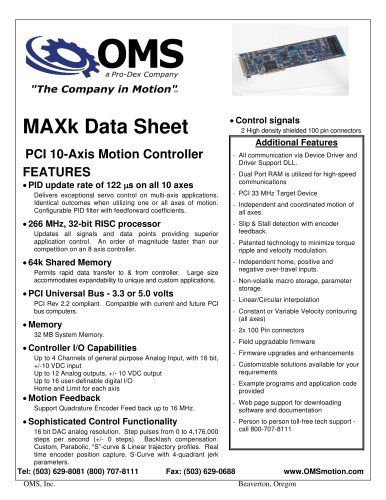
MAXp Multi-Axis Motion Controller0 pages
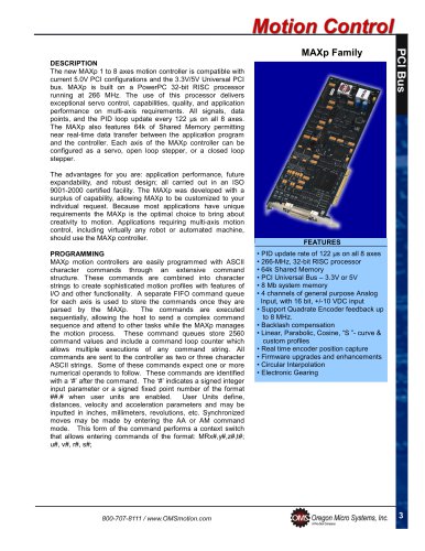
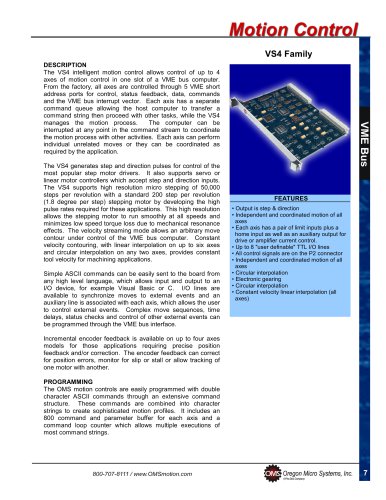
MAXp Family
DESCRIPTION
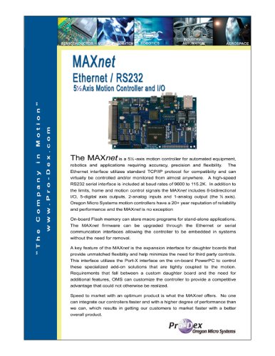
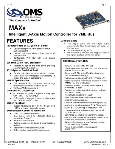
The new MAXp 1 to 8 axes motion controller is compatible with
current 5.0V PCI configurations and the 3.3V/5V Universal PCI
bus. MAXp is built on a PowerPC 32-bit RISC processor
running at 266 MHz. The use of this processor delivers
exceptional servo control, capabilities, quality, and application
performance on multi-axis requirements. All signals, data
points, and the PID loop update every 122 µs on all 8 axes.
The MAXp also features 64k of Shared Memory permitting
near real-time data transfer between the application program
and the controller. Each axis of the MAXp controller can be
configured as a servo, open loop stepper, or a closed loop
stepper.
The advantages for you are: application performance, future
expandability, and robust design; all carried out in an ISO
9001-2000 certified facility. The MAXp was developed with a
surplus of capability, allowing MAXp to be customized to your
individual request. Because most applications have unique
requirements the MAXp is the optimal choice to bring about
creativity to motion. Applications requiring multi-axis motion
control, including virtually any robot or automated machine,
should use the MAXp controller.
PROGRAMMING
MAXp motion controllers are easily programmed with ASCII
character commands through an extensive command
structure. These commands are combined into character
strings to create sophisticated motion profiles with features of
I/O and other functionality. A separate FIFO command queue
for each axis is used to store the commands once they are
parsed by the MAXp.
The commands are executed
sequentially, allowing the host to send a complex command
sequence and attend to other tasks while the MAXp manages
the motion process. These command queues store 2560
command values and include a command loop counter which
allows multiple executions of any command string. All
commands are sent to the controller as two or three character
ASCII strings. Some of these commands expect one or more
numerical operands to follow. These commands are identified
with a ‘#’ after the command. The ‘#’ indicates a signed integer
input parameter or a signed fixed point number of the format
##.# when user units are enabled.
User Units define,
distances, velocity and acceleration parameters and may be
inputted in inches, millimeters, revolutions, etc. Synchronized
moves may be made by entering the AA or AM command
mode. This form of the command performs a context switch
that allows entering commands of the format: MRx#,y#,z#,t#;
u#, v#, r#, s#;
FEATURES
• PID update rate of 122 µs on all 8 axes
• 266-MHz, 32-bit RISC processor
• 64k Shared Memory
• PCI Universal Bus – 3.3V or 5V
• 8 Mb system memory
• 4 channels of general purpose Analog
Input, with 16 bit, +/-10 VDC input
• Support Quadrate Encoder feedback up
to 8 MHz.
• Backlash compensation
• Linear, Parabolic, Cosine, “S ”- curve &
custom profiles
• Real time encoder position capture
• Firmware upgrades and enhancements
• Circular Interpolation
• Electronic Gearing
3
"