عضویت
عضویت  ورود اعضا
 راهنمای خرید


SL40.3010 pages
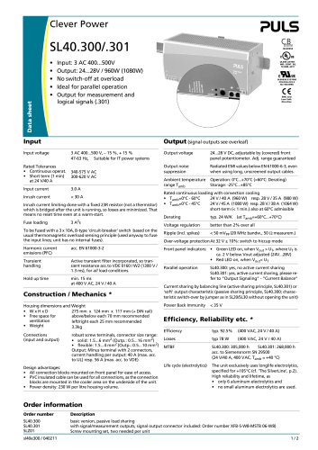
Clever Power
CB
scheme
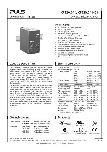
SL40.300/.301
Data sheet
•
•
•
•
•
IEC60950
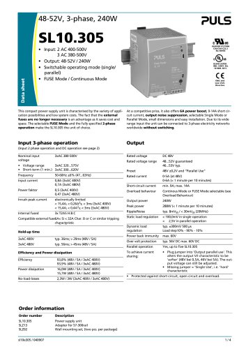
Input: 3 AC 400...500V
Output: 24...28V / 960W (1080W)
No switch-off at overload
Ideal for parallel operation
Output for measurement and
logical signals (.301)
Input
Input voltage
3 AC 400...500 V, – 15 %, + 15 %
47-63 Hz, Suitable for IT power systems
340-575 V AC
300-620 V AC
Input current
3.0 A
Inrush current
< 30 A
Inrush current limiting done with a fixed 23R resistor (not a thermistor)
which is bridged after the unit is running, so losses are minimized. That
means no reset time even at a warm-start.
3 A2s
To be fused with a 3 x 10A, B-type 'circuit-breaker' switch based on the
usual thermomagnetic overload sensing principle (used anyway to fuse
the input lines; unit has no internal fuses).
Harmonic current
emissions (PFC)
acc. EN 61000-3-2
Transient
handling
Active transient filter incorporated, so transient resistance acc.to VDE 0160 / W2 (1300 V /
1.3 ms), for all load conditions.
Hold up time
min. 15 ms
at 400 V AC, 24 V / 40 A
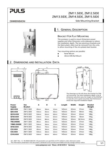
Construction / Mechanics *
Housing dimensions and Weight
275 mm x 124 mm x 117 mm (+ DIN rail)
• WxHxD
above/below each 70 mm recommended
• Free space for
ventilation
left/right each 25 mm recommended
• Weight
3.3kg
Connections
(input and output)
UL60950 E137006
CUL/CSA-C22.2
No 950-M90
EMC and
Low Volt.
Directive
Output (signal outputs see overleaf)
Rated Tolerances
• Continuous operat.
• Short term (1 min)
at 24 V/40 A
Fuse loading
UL508 LISTED
IND. CONT. EQ.
18 WM, 60°C
robust screw terminals, connector size range:
• solid: 1.5...6 mm2 (Outp.: 0.5...16 mm2)
• flexible: 1.5...4 mm2 (Outp.: 0.5...10 mm2)
Output: Minus terminal with 2 connectors,
current handling per output: 40 A (max. acc.
to UL) resp. 56 A (max. acc. to VDE)
Design advantages:
• All connection blocks mounted on front panel for ease of access.
• PVC insulated cable can be used for all connections, as the connection
blocks are mounted in the cooler area on the underside of the unit.
• Power density: 230 W per litre housing volume.
Output voltage
24...28 V DC, adjustable by (covered) front
panel potentiometer. Adj. range guaranteed
Output noise
suppression
Radiated EMI values below EN 61000-6-3, even
when using long, unscreened output cables.
Ambient temperature
range Tamb
Operation: 0°C...+70°C (>60°C: Derating)
Storage: -25°C...+85°C
Rated continuous loading with convection cooling
• Tamb=0°C - 60°C
24 V / 40 A (960 W) resp. 28 V / 35 A (980 W)
• Tamb=0°C - 45°C
24 V / 45 A (1080 W) resp. 28 V / 38 A (1064 W)
short-term (< 1 min.) also at 60°C admissible
Derating
typ. 24 W/K
Voltage regulation
better than 2% over all
(at Tamb=+60°C...+70°C)
Ripple (incl. spikes)
< 50 mVPP (20 MHz bandw., 50 Ω measurem.)
Over-voltage protection At 32 V ± 10%: switch to hiccup mode
Front panel indicators: • Green LED on, when Vout > UT, where UT is
ca. 2 V below Vout adjusted (24V...28V)
• Red LED on, when Vout< UT
Parallel operation
SL40.300: yes, no active current sharing
SL40.301: yes, active current sharing, please refer to “Output Signaling” - “Current Balance”
Current sharing by balancing line (active sharing principle, SL40.301) or
’soft’ output characteristic (passive sharing principle, SL40.300; characteristic switch-over by jumper as in SL20/SL30 without opening the unit)
Power Back Immunity
< 35 V
Efficiency, Reliability etc. *
Efficiency
typ. 92.5%
(400 VAC, 24 V / 40 A)
Losses
typ 78 W
(400 VAC, 24 V / 40 A)
MTBF
SL40.300: 305,000 h
SL40.301: 268,000 h
acc. to Siemensnorm SN 29500
(24 V/40 A, 400 VAC, Tamb = +40 °C)
Life cycle (electrolytics)
The unit exclusively uses longlife electrolytics,
specified for +105°C (cf. ’The SilverLine’, p.2).
High reliability and lifetime, as
• only 6 aluminum electrolytics and
• no small aluminum electrolytics are used.
Order information
Order number
Description
SL40.300
SL40.301
SLZ01
basic version, passive load sharing
with signal/measurement outputs, signal output connector included: Order number XFB-S-W8-MSTB 06-W8)
Screw mounting set, two needed per unit
sl40e300 / 040211
1/2
"